RGB Spectrum MediaWall 2000 Скачать руководство пользователя страница 30

O P E R A T I O N S

Window Properties

350-8799

MediaWall 2000 User’s Guide

24

. . . . .

I D E N T I F Y I N G   A   W I N D O W

WCP provides a means to locate a window position on the wall by 
flashing the window on and off for a short period of time.

To identify a specific window use the following procedure:

Move the cursor over the window that you wish to identify and 
right click on the window. You should see a pop up option menu 
similar to that shown in the following figure. 

Figure 3-14.  

Identifying a Window

Using the mouse highlight 

Identify

 option.

Click the left mouse button to complete the operation.
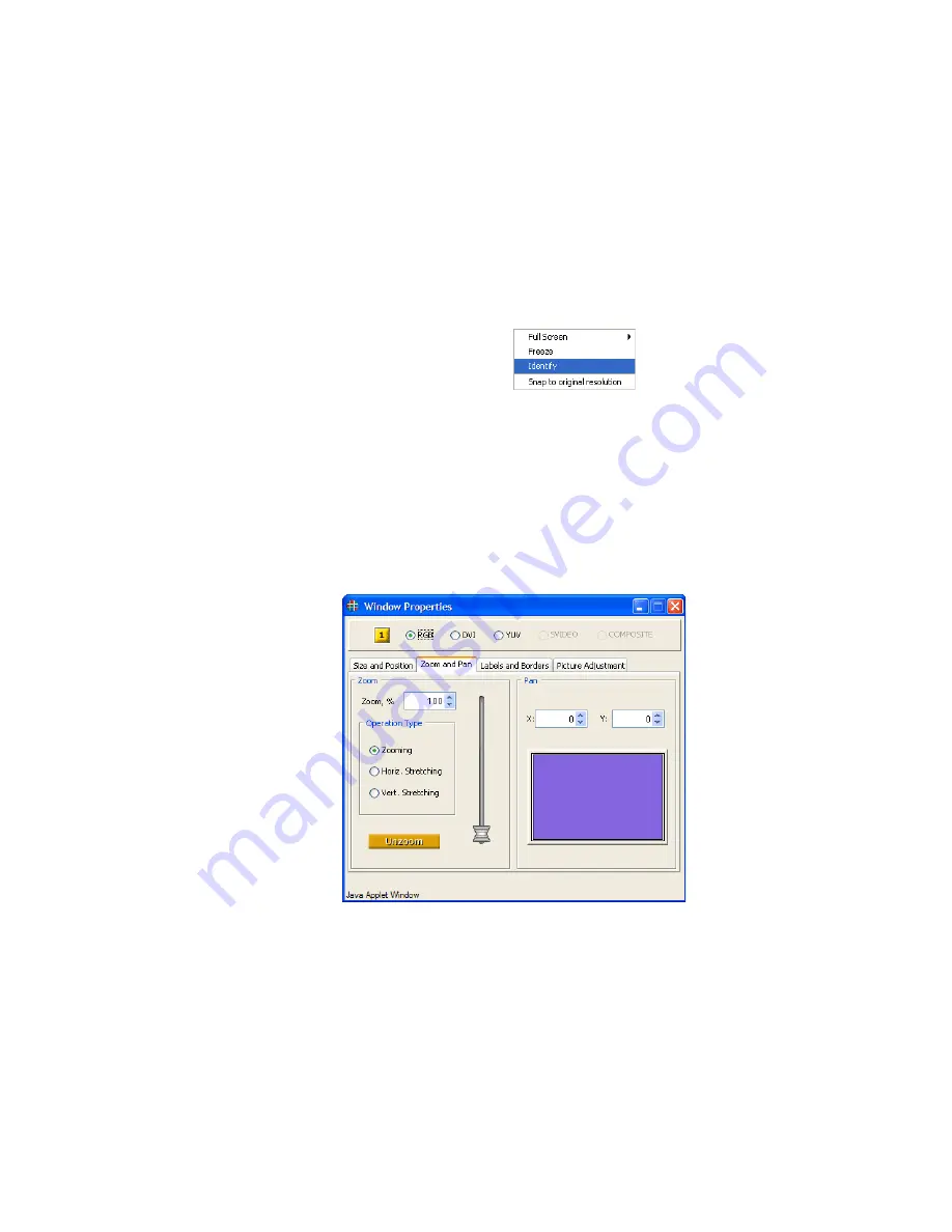
ZOOMING & PAN

 . . . . . . . . . .

WITHIN A WINDOW

The image within each window can be zoomed and panned within the 
window.  Zoom and Pan are applied to each window independently.

Figure 3-15.  

WCP Pan and Zoom Page

S E T T I N G   T H E   Z O O M   L E V E L

Zoom may be applied to the image to change without affecting the 
aspect ratio of the image, or can be applied independently to stretch the 
image in either the vertical or horizontal dimensions.  Additionally both 
interactive adjustment and numeric entry methods are supported.

Содержание MediaWall 2000

Страница 1: ...MediaWall 2000 User s Guide ...

Страница 2: ... form without prior written approval from RGB Spectrum Inc MediaWall is a registered trademark of RGB Spectrum Inc NOTICE RGB Spectrum reserves the right to make any modification to this guide or the information contained herein at any time without notice All features functions and specifications are subject to change without notice or obligation COMPANY ADDRESS RGB Spectrum 950 Marina Village Pkw...

Страница 3: ...l have no obligations under this warranty with respect to any defect unless it receives notice and a description of such defect no later than five 5 business days following the expiration of the warranty period THE WARRANTIES STATED HEREIN ARE IN LIEU OF ALL OTHER WARRANTIES EXPRESS OR IMPLIED INCLUDING BUT NOT LIMITED TO ANY IMPLIED WARRANTIES OF MERCHANTABILITY OR FITNESS FOR A PARTICULAR PURPOS...

Страница 4: ...hapter 5 System Connections 6 Graphics Input Connections 6 Video Input Connections 7 Control Connections 7 Power Connections 7 Web Control Panel WCP Connection 8 IP Address 8 Connecting to the Web Control Panel 9 System Setup 13 Wall Configuration 13 Mullion Adjustment 14 Overlap Adjustment 14 Output Setup 14 Input Setup 14 Chapter 3 Operations 15 In This Chapter 15 Web Control Panel Overview 16 W...

Страница 5: ... Background Colors 30 Background Images 31 Loading Background Images 31 Foreground Controls 32 Graphical Image 34 Foreground Clock Object 35 Setting the Clock 35 Cursor Mode 36 Positioning Foreground Objects 36 Precise Positioning 36 Interactive Positioning 37 Window Layouts 38 Window Presets 40 Window Presets 40 Chapter 4 Advanced Setup 41 In This Chapter 41 Configuration 42 Wall Configuration 42...

Страница 6: ...Test Pattern 57 Background Foreground Images 59 Image Specifications 59 Background Images 59 Foreground Images 59 Alpha Channels 60 Compact Flash Card Formatting 61 Compact Flash File Names 62 Adding Graphics to the Compact Flash Card 62 Adding Graphics via Card Reader Writer 62 Adding Graphics via WCP 63 Using Compact Flash Card Graphics 64 Appendix A Contact Information 65 How to Contact RGB Spe...

Страница 7: ...can be controlled in real time by serial RS 232 or Ethernet 10 100 Base T control ports WALL CONFIGURATIONS The MediaWall 2000 can display up to 6 graphics windows and 6 video windows simultaneously for display on up to four display devices arranged as a linear horizontal wall 1 x 2 1 x 3 1 x 4 or a two dimensional 2x2 wall array The following figure shows a schematic view of a MediaWall 2000 driv...

Страница 8: ...ports zoom and pan within a window and input freezing User defined presets MediaWall 2000 stores and recalls up to twenty four user defined display arrangement presets each containing information about window size and position image controls and image positioning on screen Remote control Complete system control is supported via the RS 232 serial port or the 10 100 BaseT Ethernet port Many control ...

Страница 9: ...cassette recorders DVD players or video teleconferencing systems SYSTEM OUTPUTS As standard the system provides six output channels configured with DVI I connectors Each connector supports both one RGB analog or one digital output All input signals to the MediaWall 2000 are converted to the selected output resolution adjustable up to 1920 pixels by 1200 lines with horizontal scan rates ranging fro...

Страница 10: ... HDTV YPbPr input with tri level sync Optional DVI inputs up to 1920 x 1200 60Hz Video inputs are selectable between S Video and Composite formats in both NTSC and PAL video standards Outputs Six dual output connectors each support DVI and RGB analog signals Analog RGB output up to 1920 x 1200 60 Hz DVI output up to 1920 x 1200 60Hz Adjustable output gamma to optimize performance with a variety of...

Страница 11: ...TION SETUP IN THIS CHAPTER This section provides installation and setup information of the MediaWall 2000 system with a variety of wall configurations The following topics are discussed System Connections Web Control Panel WCP Connection System Setup ...

Страница 12: ...ormation Figure 2 1 MediaWall 2000 Rear View GRAPHICS INPUT CONNECTIONS Each graphics window windows 1 6 supports the connection of both an analog RGB YPbPr signal and a digital DVI signal Figure 2 2 Graphics Input Connectors Analog RGB 15 pin female sub miniature D connector Digital DVI 29 pin Molex connector Note Before proceeding with this section make sure that the front panel power switch is ...

Страница 13: ...ther a serial RS 232 control port or a 10 100 Base T Ethernet port RS 232 serial port Female 9 pin sub miniature D connector Ethernet 10 100 Base T RJ 45 modular connector To connect MediaWall 2000 to a network use a standard Ethernet cable To connect MediaWall 2000 directly to a computer use an Ethernet crossover cable or a hub POWER CONNECTIONS The typical power consumption of a MediaWall 2000 i...

Страница 14: ...terface provides a graphical alternative to the command line setup and control used with serial or telnet control The WCP uses the MediaWall 2000 s internal Web Server allowing you to set up and operate the system from a standard browser S Please note the following important recommendations To minimize compatibility issues between browsers it is recommended that you use the Internet Explorer web b...

Страница 15: ...rs Refer to the network settings help section of your computer operating system OS for assistance with setting the control computer s IP address Subnet Mask and Gateway Refer to IP Address page 8 for more information on the MediaWall 2000 and control computer s IP address requirements LAN connection connect the MediaWall 2000 10 100 Base T Ethernet Port to a local area network LAN From a computer ...

Страница 16: ...dress Entry If the network connection is working properly and the correct IP address has been entered MediaWall 2000 responds by displaying the WCP Startup Screen page shown in the following figure Figure 2 6 WCP Startup Screen Note MediaWall 2000 is configured at the factory to have the default IP address 192 168 1 200 Before connecting the MediaWall 2000 to the network you must make sure that th...

Страница 17: ...rning Choose Open and the WCP will download from the MediaWall 2000 The Media Wall Control Panel Console window will then open which detects the MediaWall 2000 s IP address Figure 2 8 MediaWall Control Panel Console Another window will open asking for a login password to launch the WCP Type RGB and click on OK Note If the default password RGB has been changed you will need to enter that new passwo...

Страница 18: ...l Screen launches displaying the current wall configuration see Figure 2 10 below This window provides access to other floating windows for GUI control of MediaWall 2000 functions Figure 2 10 WCP Virtual Screen Note You must follow the procedures outlined in the next section System Setup to ensure proper configuration and operation of MediaWall 2000 ...

Страница 19: ...l Screen Figure 2 10 click the Setup menu Click on the Configuration tab Use the drop down box in the Wall Configuration section to select the type of wall that you plan to use in your installation e g 1x3 2x2 Figure 2 11 WCP Wall configuration page Note If you make a change to the wall configuration you will be asked to confirm the change see below If you choose Yes then another alert box will op...

Страница 20: ... The output format should be selected to match the requirements of the displays you will be using in the wall This may be accomplished automatically using the Output Timing Tab of the Setup Page see Output Timing page 50 INPUT SETUP The MediaWall 2000 has both video composite and S Video and graphics RGB and DVI inputs Video inputs require no setup and can be connected and then used without furthe...

Страница 21: ... with standard web browsers such as Microsoft Internet Explorer Topics discussed in this chapter include Web Control Panel Overview Window State and Priority Control Window Properties Background Controls Foreground Controls Window Layouts Window Presets Note Before you begin using the WCP you must follow the information contained in Web Control Panel WCP Connection page 8 and System Setup page 13 ...

Страница 22: ...ively Move and Size Individual Windows Save and Recall Window Display Arrangement Presets registers Adjust Brightness Contrast and other Parameters Add Borders and or Labels to Individual Windows Zoom Pan and Freeze Individual Inputs Within a Window Access Configuration and Setup Windows WCP VIRTUAL SCREEN The MediaWall 2000 WCP Virtual Screen is shown in the following figure Figure 3 1 Web Contro...

Страница 23: ...enu structure which are discussed in this chapter Figure 3 3 WCP Window and Operation Menus For information on the MediaWall 2000 WCP Setup menu please see Chapter 4 Advanced Setup page 41 WCP WINDOW SELECTION When utilizing some menus on the WCP you are able to change the target window for your menu changes This is very useful when you did not select the desired window before opening a menu To us...

Страница 24: ...nable buttons in the WCP Window State and Priority Control window An enabled window is indicated by the green button color Click on the desired window button to turn the display ON or OFF Figure 3 7 Window State and Priority Control Window OVERLAPPING WINDOWS Windows may be positioned anywhere over the wall and can be placed to overlap other windows When windows overlap they are layered in order o...

Страница 25: ...ay be affected For example if Window 10 currently has the priority level 10 then promoting the window to have a priority level of 2 will demote the priority of all the windows from 2 down to 11 WINDOW PROPERTIES SELECTING A WINDOW INPUT Each window supports two types of input sources selectable from any of the Window Properties pages Windows 1 6 are graphics windows that accept the following input...

Страница 26: ...ee Advanced Setup page 41 SETTING WINDOW SIZE POSITION Setting size and position of any window on the wall using the WCP can be a simple click and drag operation If more control is required you can enter numbers manually too To move a window position the cursor over the window click and drag the window to the new position To size a window click and grab the edge of the picture and drag to stretch ...

Страница 27: ...ed Note that you can enter the numeric values directly into the spin box Complete the entry by pressing the keyboard ENTER key To set the position use the Position X and Y spin boxes as required Note that you can enter the numeric values directly into the spin box Complete the entry by pressing the keyboard ENTER key R E S E T T I N G WI N D O W S I Z E WCP also provides a convenient means to rest...

Страница 28: ...illustrated in the following figure Figure 3 11 Selecting the Snap Option Highlight the option Snap to original resolution and click to select it The window size will then be set to correspond to the native size and the image will be displayed at the native size within the window ...

Страница 29: ...by highlighting the option and using the left mouse button to select the desired option S Example Use the selected window to fill the third element of the wall Follow the procedure above and select Display 3 from the drop down option box as shown in Figure 3 12 F R E E Z I N G A W I N D O W WCP provides a means to freeze the contents of any window displayed on the wall To freeze a specific window ...

Страница 30: ...he following figure Figure 3 14 Identifying a Window Using the mouse highlight Identify option Click the left mouse button to complete the operation ZOOMING PAN WITHIN A WINDOW The image within each window can be zoomed and panned within the window Zoom and Pan are applied to each window independently Figure 3 15 WCP Pan and Zoom Page S E T T I N G T H E Z OO M L E V E L Zoom may be applied to the...

Страница 31: ...iginal image size click on the Unzoom button at the bottom of the Zoom pane P A N N I N G W I T H I N A W I N D O W When an image is zoomed inside of a window the image may be panned around inside the window This may be accomplished interactively or numerically by entering X and Y position into the pan numeric entry buttons To pan using the interactive method use the following procedure Click the ...

Страница 32: ...Selected Window icon and click the desired window number in the resulting pop up see WCP Window Selection page 17 for information Set the border width as required using the Width spin box control Click the Border Enabled check box to turn on the border To change the border color around a window use the following procedure Click the Properties menu Select the Window Label and Borders Page tab Figur...

Страница 33: ...r in the resulting pop up see WCP Window Selection page 17 for information Enter the label text into the Label Entry box The label may be up to 23 characters in length and may consist of any readable ASCII characters except for spaces Click the Label Enabled check box The label may be positioned above or below the window You may also choose to position in the center or justified to the left or rig...

Страница 34: ...s of inputs Brightness Contrast Saturation Hue In addition to the parameters above S Video and Composite inputs also have the following adjustments Scan Mode Aspect Ratio Sharpness To change the Brightness Contrast Saturation and or Hue for a selected window use the following procedure Click the Properties menu Select the Picture Adjustment Page tab Figure 3 17 If the selected window is not correc...

Страница 35: ...ctor button to the right of each parameter to increase or decrease the adjustment To change the Scan Mode Aspect Ratio and or Sharpness for a selected video window use the following procedure Click the Properties menu Select the Picture Adjustment Page tab Figure 3 17 If the selected window is not correct click on the Selected Window icon and click the desired window number in the resulting pop up...

Страница 36: ...ce of selecting either a pre defined color background or a custom color background Use the following procedure to select a background color Click the Controls menu Select the Background page tab Figure 3 18 Choose a solid color Click on the desired colored button to choose a solid background color OR Choose a custom color Click on the multi colored button at the right end of the row of colored but...

Страница 37: ...O A D I N G B A C K G R O U N D I M A G E S Images to be used as backgrounds on the MediaWall 2000 are loaded in a slightly different manner than colored backgrounds Follow the steps below to load and use a background image Click the Controls menu Select the Background page tab Figure 3 18 Choose an image from the Image List section of the page Figure 3 19 Figure 3 19 WCP Background Image List Are...

Страница 38: ...ha Channels page 60 Clock optional An optional digital clock can be selected for display on the output Cursor optional An optional on screen cursor can be used to illustrate relevant material on the wall output as well as move and resize output windows A foreground object can be positioned on the wall within any of the individual displays However it cannot be positioned over the boundary between d...

Страница 39: ...O P E R A T I O N S Foreground Controls 350 8799 MediaWall 2000 User s Guide 33 the Operation Controls menu as shown in Figure 3 20 Figure 3 20 WCP Foreground Object Page ...

Страница 40: ... you must select and load the desired image file from the Image List area Figure 3 21 WCP Foreground Image List Area Use the following procedure to load a foreground image Click the Controls menu Select the Foreground page tab Figure 3 20 Choose an image from the Image List section of the page Figure 3 21 Click Load to use the selected image as the foreground object Note Scaling is not applied to ...

Страница 41: ...t the display format 12 or 24 hour and set the clock to the current time see Setting the Clock page 35 Position the object wherever you would like by following the steps in Positioning Foreground Objects page 36 S E T T I N G T H E C L OC K If you have chosen the clock as the foreground image see Foreground Clock Object page 35 the Clock Setup area of the window is automatically loaded as shown in...

Страница 42: ...ry and resize it as desired When you are finished with the Cursor mode close the Cursor Pad window by clicking the X symbol in the upper right corner Figure 3 23 Close Window Icon POSITIONING FOREGROUND OBJECTS Clock and Image foreground objects may be placed anywhere on screen by one of the following methods Position precisely enter the x and y coordinates of the object Interactive dragging an ic...

Страница 43: ...ls page 32 Using your mouse position the cursor over the Object box displayed in the Wall Configuration area at the botom of the Foreground page Figure 3 24 Figure 3 24 WCP Wall Configuration Area Hold down the left mouse button and move the cursor to the position where you wish the foreground object to appear Release the left button to complete the positioning operation Note that images can be po...

Страница 44: ...all arrays For example there are different window layouts for a 2x2 wall in comparison with a 1x3 wall Make sure that you have set your wall configuration correctly before choosing a wall layout All predefined wall layouts are designed to maintain the original aspect ratio of the input image and to fit all windows on the wall without requiring overlap of any window You can if you wish reposition w...

Страница 45: ...s using the Next and Previous buttons at the top of the Window Layouts page A visual representation will be shown of the selected layout in the screen in the center of the Layouts page Each layout has a unique identification number associated with it This is indicated in the Current Layout entry box at the bottom of the Window Layouts page If you know the number of the layout that you wish to you ...

Страница 46: ...uttons are located at the bottom of the WCP Virtual Screen see Figure 3 26 above To save the Window settings to a Window Preset Register use the following procedure Make all the window settings that you require using the procedures detailed in previous sections Click the Save button at the bottom right of the WCP window Click the Preset button that you wish to use to save your current settings int...

Страница 47: ...the MediaWall 2000 Technical Reference Manual for information Topics discussed in this chapter include Configuration Input Timing Output Timing System Settings Administrator Options Test Patterns Background Foreground Images The advanced setup functions outlined in this chapter require access to the Web Control Panel via a standard Web browser See Web Control Panel WCP Connection on page 8 for det...

Страница 48: ...tion deals with the alignment aids that MediaWall 2000 provides WALL CONFIGURATION MediaWall 2000 can be configured for use with horizontal walls from 1x2 to 1x4 as well as 2x2 walls Before you can align the wall you must set the MediaWall 2000 for the wall configuration that you will be using Figure 4 2 WCP Setup Configuration Page To set the wall configuration the following procedure Click the S...

Страница 49: ...he manufacturers instructions for best results Because each cube has it s own controls for size and position these controls are not duplicated by MediaWall 2000 Note that color adjustments can be made at a later time following wall alignment MULLIONS OVERLAP COMPENSATION Typically there is a small frame called a mullion around the active display area of the individual display device This represent...

Страница 50: ...dth in pixels can be obtained by measuring the size of the outside dimension of the cube and the physical dimension of the active area The mullion width cube exterior dimension active area dimension x number of pixels Both mullions and overlap use the same entry boxes If you enter a positive number this is a mullion compensation and the entry box labels display Mullion X and Mullion Y If you enter...

Страница 51: ...into the entry box Mullion X or Overlap X Enter a positive number for Mullions or a negative number for Overlap Enter the vertical Y mullion or overlap size into the entry box Mullion Y or Overlap Y Enter a positive number for Mullions or a negative number for Overlap A good way to test your mullion settings is to view the wall using a test image that has a diagonal line passing through the mullio...

Страница 52: ... CURRENT TIMING SETTINGS The timing parameters displayed in the upper section of the page relate to the selection in the drop down box which may not be the same as those currently used To view the current settings click in the check box Show Timing Values and the current values will be displayed in red in the associated parameter boxes LOADING FROM THE TIMING LIST If the MediaWall 2000 does not pr...

Страница 53: ...r input signal You may find an entry in the list that is very close to your parameters and in this case you can load the entry modify it and then save the new entry to the user defined timing list There are over 100 available user entries Use the following procedure to create a new user defined entry in the timing list Click the Edit button in the Input Timing section of the Input Timing page Ente...

Страница 54: ...rner of the input image in the desired location at the top left of the display Click the radio button labeled Bottom Right Use the Up Down Left Right adjustment buttons in the Interactive Adjustment section to position the lower right corner of the input image in the desired location at the lower right corner of the display Recheck the Top Left corner of the image and readjust as needed to positio...

Страница 55: ...the image may appear to have noisy or indistinct edges Use the following procedure to set the ADC phase Be sure that the input signal has a lot of high frequency detail In the Input Timing section of the Input Properties page click on the UP button next to the ADC clock phase spin box and view the output image If the image quality deteriorates click on the DOWN button and continue clicking on the ...

Страница 56: ...g Values and the current values will be displayed in red in the associated parameter boxes LOADING FROM THE TIMING LIST If you know the timing parameters of the output signal for the display device you can manually load the timing from the either the factory timing list or the user defined timing list Use the following procedure to load a new output timing set Click the Setup menu Click on the Out...

Страница 57: ...he new entry Figure 4 11 Timing List Name dialog box Enter a name for the new timing entry and click OK The name can be up to 23 characters in length and can contain upper and lower and numeric characters Avoid the use of a space or the or characters INTERACTIVE TIMING If you do not know the exact timing parameters for an output signal you can adjust the timing parameters interactively so that you...

Страница 58: ...ned of the image and readjust as needed to position the image in the bottom right corner of the display Perform the previous two steps if necessary until you are satisfied that both corners of the image are correctly positioned From the timing scroll list select a new entry above 100 to save your new timing parameters Click the SAVE button A dialog box will open allowing you to name the new entry ...

Страница 59: ...Wall 2000 These include the following Host Name IP Address Subnet Mask Default Gateway To change the parameters listed above use the following procedure Click the Setup menu Select the System Page Figure 4 13 Select the desired parameter field in the Network Settings area of the window Type in the desired information Click Apply to save the changes and apply them to the MediaWall 2000 OR Click Can...

Страница 60: ...ith a terminal emulator you will probably want to have the serial port echo turned on which is the default setting In some control applications you may want to disable echo To turn the serial port echo OFF use the following procedure Click the Setup menu Select the System Page Figure 4 13 Click on the Echo On check box to deselect or select serial port Echo ADMINISTRATOR OPTIONS The MediaWall 2000...

Страница 61: ...ure 4 14 WCP Setup Administrator Page To change Telnet and WCP passwords follow the steps below Click the Setup menu Select the Administrator Page Figure 4 14 Click the Change Password button The page changes to reveal the options shown below Figure 4 15 WCP Administrator Change Password Page ...

Страница 62: ...password in the left box and again to confirm it in the right box Click Ok to save the new password or Cancel to leave the original password unchanged This new password will be required the next time you launch the WCP and or begin a Telnet session Note If you do not have the optional software feature only the Administrator radio button will be accessible ...

Страница 63: ...image characteristics and assist in alignment The following test patterns are available Table 4 1 MediaWall 2000 Internal Test Pattern Signals Pattern Description BARS 100 saturated Vertical color bars BARS 75 75 saturated Vertical color bar STEPS Grey scale steps MOIRE High resolution test signal RAMP Linear grey ramp signal REDRAMP Linear red ramp signal GREENRAMP Linear green ramp signal BLUERA...

Страница 64: ...al Selection To select a Test Pattern use the following procedure Click the Controls menu Select the Background page Figure 4 16 Select the desired test pattern from the Test Pattern drop down list at the bottom of the page NOTE To disable the test pattern use the Test Pattern drop down box and select OFF ...

Страница 65: ... B A C K G R OU N D I M A G E S Background images on the MediaWall 2000 can be either JPEG or TIFF formats Size the background image in pixels to be the same size as the total wall image Note that if there are any mullions you should size the image to include the mullions S For example if you have a 2 x 2 wall with individual displays of 1024 x 768 pixels and mullions that are 20 pixels H x 15 pix...

Страница 66: ...arent when placing it over a background image The alpha channel should be white for the parts you wish to be viewable on screen and black for those parts you wish to be fully transparent For example you can place a round logo over the window output as a circle instead of its natural square shape as shown in the following illustration Figure 4 17 Alpha Channel Illustration Logo Alpha Channel Wall O...

Страница 67: ...md into the Open dialog box 5 Click the OK button to open the Command Window 6 Type the following in the command window format CF_Drive_Letter FS FAT A 2048 Where CF_Drive_Letter represents the drive number that you noted in step 1 of this procedure S Example Format a compact flash card that is mounted as drive E on your computer On the command line type the following format E FS FAT A 2048 7 Pres...

Страница 68: ...uggested that you embed information about the image resolution into the file name S Example MAP2_3200x2400 jpg ADDING GRAPHICS TO THE COMPACT FLASH CARD Once you have an appropriately formatted and configured compact flash card you can copy files to the card using one of two methods a PC equipped with a compact flash reader writer or via the Web Control Panel A D D I N G G R A P H I C S V I A C A ...

Страница 69: ...front panel card slot Click the Controls menu of the WCP Select the Background or Foreground page tab Figure 4 16 depending on which type of graphic image you are adding Click the Add button A file browser window opens Figure 4 19 allowing you to navigate to the desired image If you do not see the file listed turn off the automatic file type filtering by clicking the Files of type pull down menu a...

Страница 70: ...ages 350 8799 MediaWall 2000 User s Guide 64 USING COMPACT FLASH CARD GRAPHICS Graphic images stored on the compact flash card can be loaded as background or foreground images See Background Controls page 30 and Foreground Controls page 32 for details ...

Страница 71: ...RUM RGB Spectrum can be reached via phone fax mail and e mail as listed below RGB Spectrum 950 Marina Village Parkway Alameda CA 94501 Phone 510 814 7000 Fax 510 814 7026 E Mail technical support support rgb com E Mail sales and product information sales rgb com Website http www rgb com ...

Отзывы: