RF-Star BM-ND04C Скачать руководство пользователя страница 46


nRF52810 

www.szrfstar.com

                                                                                                                                                  V1.3 - Sep., 2020 

Shenzhen RF-star Technology Co., Ltd.                                                                                                                   

Page  45  of  50


10.3 Basic Operation of Hardware Design 

1. 

It is recommended to offer the module with a DC stabilized power supply, a tiny power supply ripple coefficient and 

the reliable ground. Please pay attention to the correct connection between the positive and negative poles of the 

power supply. Otherwise, the reverse connection may cause permanent damage to the module; 

2. 

Please ensure the supply voltage is between the recommended values. The module will be permanently damaged 

if the voltage exceeds the maximum value. Please ensure the stable power supply and no frequently fluctuated 

voltage. 

3. 

When designing the power supply circuit for the module, it is recommended to reserve more than 30% of the margin, 

which is beneficial to the long-term stable operation of the whole machine. The module should be far away from the 

power electromagnetic, transformer, high-frequency wiring and other parts with large electromagnetic interference. 

4. 

The bottom of module should avoid high-frequency digital routing, high-frequency analog routing and power routing. 

If it has to route the wire on the bottom of module, for example, it is assumed that the module is soldered to the Top 

Layer,


the copper must be spread on the connection part of the top layer and the module, and be close to the digital 

part of module and routed in the Bottom Layer (all copper is well grounded).   

5. 

Assuming that the module is soldered or placed in the Top Layer, it is also wrong to randomly route the Bottom Layer 

or other layers, which will affect the spurs and receiving sensitivity of the module to some degrees; 

6. 

Assuming that there are devices with large electromagnetic interference around the module, which will greatly affect 

the  module  performance.  It  is  recommended  to  stay  away  from  the  module  according  to  the  strength  of  the 

interference. If circumstances permit, appropriate isolation and shielding can be done. 

7. 

Assuming that there are routings of large electromagnetic interference around the module (high-frequency digital, 

high-frequency analog, power routings), which will also greatly affect the module performance. It is recommended 

to stay away from the module according to the strength of the interference. If circumstances permit, appropriate 

isolation and shielding can be done. 

8. 

It  is  recommended  to  stay  away  from  the  devices  whose TTL  protocol  is  the  same  2.4  GHz  physical  layer,  for 

example: USB 3.0. 

9. 

The antenna installation structure has a great influence on the module performance. It is necessary to ensure the 

antenna is exposed and preferably vertically upward. When the module is installed inside of the case, a high-quality 

antenna extension wire can be used to extend the antenna to the outside of the case. 

10. 

The antenna must not be installed inside the metal case, which will cause the transmission distance to be greatly 

weakened. 

11. 

The recommendation of antenna layout. 

The inverted-F antenna position on PCB is free space electromagnetic radiation. The location and layout of antenna 

is a key factor to increase the data rate and transmission range. 

Therefore, the layout of the module antenna location and routing is recommended as follows: 

Содержание BM-ND04C

Страница 1: ...nRF52810 Bluetooth 5 0 Low Energy Slave Module and Protocol Version V1 3 Shenzhen RF star Technology Co Ltd Sep 16th 2020...

Страница 2: ...nRF52810 www szrfstar com V1 3 Sep 2020 Shenzhen RF star Technology Co Ltd Page 1 of 50 RF BM ND04C RF BM ND04I RF BM ND08...

Страница 3: ...guration at Beacon Mode 7 2 6 Device Status 8 3 Package and Pin Assignment 9 3 1 RF BM ND04C I 9 3 2 RF BM ND08C I 12 4 UART Transparent Transmission Protocol Bridge Mode 15 5 BLE Protocol Specificati...

Страница 4: ...1 7 1 Test by APP Android 31 7 2 Test by PC End 33 Preparation before Use 33 Connection Steps 34 8 iOS APP Programming Reference 39 9 Master Reference Code Transparent Transmission 42 10 Application I...

Страница 5: ...of Figures Figure 1 PCB Footprint of RF BM ND04C 9 Figure 2 PCB Footprint of RF BM ND04CI 9 Figure 3 Pin Assignment of RF BM ND04C I 10 Figure 4 PCB Footprint of RF BM ND08C 12 Figure 5 PCB Footprint...

Страница 6: ...rts Bluetooth 5 0 LE including the high speed 2 Mbps feature and ANT and 2 4 GHz proprietary protocols for simple programming The module has numerous digital peripherals and interfaces such as PDM PWM...

Страница 7: ...ign for master CPU and the APP for mobile devices In order to ensure the stability of the firmware the module will start to work normally after 500 ms of power on 2 2 Features 1 Easy to use no need of...

Страница 8: ...49 A Broadcast cycle 5000 ms Connection 64 72 A Connection cycle 50 ms Connection 33 80 A Connection cycle 100 ms 2 3 Supporting Working Mode The device supports two working modes as below 1 BLE slav...

Страница 9: ...closed and unavailable in this mode 2 6 Device Status 1 DEVICE START The device starts to work 2 S CONNECTED BLE slave is successfully connected 3 S DISCONNECTED BLE slave is disconnected 4 B CONNECTE...

Страница 10: ...of 50 3 Package and Pin Assignment 3 1 RF BM ND04C I RF BM ND04C is pin to pin compatible with and RF BM ND04CI The difference is that the antenna of RF BM ND04C is PCB type while RF BM ND04CI is IPEX...

Страница 11: ...f RF BM ND04C I Table 2 Pin Functions of RF BM ND04C I Pin Name Function Description 1 GND GND Ground 2 VCC VCC Power supply 1 7 V 3 6 V Recommended to 3 3 V 3 P21 RST I O Reset active low 4 P22 I O 5...

Страница 12: ...rial port RX 20 P09 I O 21 P10 I O 22 P11 I O 23 P12 I O 24 P13 Wakeup IO When the module is in sleep state the module can be awakened through this IO Active on falling edge 25 P14 I O 26 P15 I O 27 P...

Страница 13: ...h and RF BM ND08CI The difference is that the antenna of RF BM ND08C is PCB type while RF BM ND08CI is IPEX type SWD debugging ports are on the bottom side of the module which is not pull out in the s...

Страница 14: ...5 P17 State indicator Broadcast state indicator in high level during broadcast in low level during connection always on 6 P21 RST I O Reset active low 7 P13 Wakeup IO When the module is in sleep stat...

Страница 15: ...tar Technology Co Ltd Page 14 of 50 that the device is ready to recei 16 P07 CTS Clear ToSend send permission input signal used to judge whether it can send data to the other party active low 17 P06 T...

Страница 16: ...mobile devices to the module must be sub packed automatically into 1 244 Bytes packet before sending The module will transmit them to the master RXD in turn when received the packets 1 The hardware pr...

Страница 17: ...UUID Characteristics UUID 6E400003B5A3F393E0A9E50E24DCCA9E Executable operations Notify Remarks The serial port input is transmitted to the BLE output and the data input from the serial port RX will b...

Страница 18: ...has the above four types of commands 4 The AT command must be capitalized and ended with a carriage return and line feed CRLF 5 The returned in the query AT command indicates the optional parameters a...

Страница 19: ...t save after power off AT ROLE Query set device role Take effect after restart save after power off AT POWER Query set device power Take effect after restart save after power off AT SLEEP Query set sl...

Страница 20: ...on Query device name Example AT NAME Return Value AT NAME RF STAR SMMT OK Remark AT NAME Function Set device name Example AT NAME TEST NAME Return Value OK Remark Take effect after restart save after...

Страница 21: ...unction Set device MAC address Example AT MAC F1 F2 F3 F4 F5 F6 Return Value OK Remark Take effect after restart save after power off Serial Port Echo AT ECHO Function Query parameter range of this co...

Страница 22: ...this command Example AT STATUS Return Value AT STATUS 0 1 OK Remark This command has two parameters 0 Disable device status display 1 Enable device status display AT STATUS Function Query the current...

Страница 23: ...e current role Example AT ROLE Return Value AT ROLE 0 OK Remark The current role of the device is slave AT ROLE Function Set device role Example AT ROLE 1 Return Value OK Remark The device will work i...

Страница 24: ...e Broadcast interval is 200 ms AT ADS Function Set broadcast parameters Example AT ADS 1 0 500 Return Value OK Remark Enable device broadcast Non connectable device Broadcast interval is 500 ms Take e...

Страница 25: ...ated according to different mobile phones up to the set connection interval 3 Slave Service AT SERVICE Function Query parameter range of this command Example AT SERVICE Return Value AT SERVICE 0 1 0 F...

Страница 26: ...fect after restart save after power off Disconnect Device AT DISCONNECT Function Disconnect all the current connected device Example AT DISCONNECT Return Value OK Remark Take effect immediately do not...

Страница 27: ...Remark Set Beacon company ID F1F2 Set Reference RSSI 60 Take effect after restart save after power off Tx Power AT POWER Function Query parameter range of this command Example AT POWER Return Value AT...

Страница 28: ...LE function switch Parameter 3 Serial port wake up function switch 0 Disable 1 Enable AT SLEEP Function Query current sleep status of the device Example AT SLEEP Return Value AT SLEEP 1 1 1 OK Remark...

Страница 29: ...device Example AT UART Return Value AT UART 115200 OK Remark The current baud rate is 115200 bps AT UART Function Set baud rate of the device Example AT UART 9600 Return Value OK Remark Set the baud r...

Страница 30: ...turn Value AT AUTH 1 12GH __ 15 OK Remark Parameter 1 Enable user authentication function Parameter 2 Key is 12GH __ Parameter 3 Valid time of user authentication is 15 s AT AUTH Function Set user aut...

Страница 31: ...nRF52810 www szrfstar com V1 3 Sep 2020 Shenzhen RF star Technology Co Ltd Page 30 of 50 Return Value OK Remark Device parameters restore factory settings and restart Take effect immediately...

Страница 32: ...f the module is 115200 the data bit is 8 the parity bit is none and the stop bit is 1 Open the nRFConnect to search mobile phone Bluetooth needs to be turned on a list of nearby BLE devices that are b...

Страница 33: ...nRF52810 www szrfstar com V1 3 Sep 2020 Shenzhen RF star Technology Co Ltd Page 32 of 50...

Страница 34: ...Hardware preparation PC with standard Type A USB interface RF DG 40A nRF52840 dongle RF BM ND04C I RF BM BD08C I 2 Software preparation nRF Connect for Desktop Download address https www nordicsemi c...

Страница 35: ...on click the Open button and the operation interface will appear At this time you need to select the corresponding Dongle device for normal use Click Select device to pop up the device name and then c...

Страница 36: ...M ND04C module as the slave device as an example referred to as ND04C as shown in the figure below Dongle has successfully connected the slave device ND04C 4 After the device is successfully connected...

Страница 37: ...nRF52810 www szrfstar com V1 3 Sep 2020 Shenzhen RF star Technology Co Ltd Page 36 of 50...

Страница 38: ...nRF52810 www szrfstar com V1 3 Sep 2020 Shenzhen RF star Technology Co Ltd Page 37 of 50...

Страница 39: ...nRF52810 www szrfstar com V1 3 Sep 2020 Shenzhen RF star Technology Co Ltd Page 38 of 50...

Страница 40: ...as follows method writeValue forCharacteristic withResponse param data The value to write param characteristic The characteristic on which to perform the write operation param type The type of write t...

Страница 41: ...elf setNotifyValue NO forCharacteristic c close notify enable switch method didUpdateValueForCharacteristic param peripheral Pheripheral that got updated param characteristic Characteristic that got u...

Страница 42: ...henzhen RF star Technology Co Ltd Page 41 of 50 controls on direct drive functions are similar all by reading or writing to certain characteristic The only difference is the characteristic UUID and th...

Страница 43: ...ocontroller to receive If the microcontroller has data to send BRTS will set low to notification module to receive The schematic code is as follows void main void Wait for the module start While memcm...

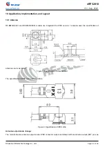
Страница 44: ...ND08CI module are integrated the IPEX version 1 antenna seat the specification of antenna seat is as follow Figure 7 Specification of Antenna Seat The specification of IPEX wire end is as follow Figur...

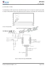
Страница 45: ...very is IPEX connector mode Under IPEX connector mode C1 is off and C2 is welded If you would like to change to half hole antenna output mode please disconnect C2 and weld C2 The locations of C1 and C...

Страница 46: ...t is also wrong to randomly route the Bottom Layer or other layers which will affect the spurs and receiving sensitivity of the module to some degrees 6 Assuming that there are devices with large elec...

Страница 47: ...ption and reflection of radio waves will be poor when the module is tested close to the ground 2 Seawater has a strong ability to absorb radio waves so the test results by seaside are poor 3 The signa...

Страница 48: ...suggest that all modules should follow the 3 precautions below 1 According to the anti static measures bare hands are not allowed to touch modules 2 Modules must be placed in anti static areas 3 Take...

Страница 49: ...p 220 235 230 250 Average Descend Rate Tp to Tmax Max 6 s Max 6 s Time from 25 to Peak Temperature t2 Max 6 minutes Max 8 minutes Time of Soldering Zone tP 20 10 s 20 10 s Figure 12 Recommended Reflow...

Страница 50: ...cification of AT commands Update communication rate Add power consumption table 2020 06 24 V1 1 Update the description 2020 08 14 V1 2 Modify the minimum broadcast interval of 20 ms Add connection int...

Страница 51: ...Y CO LTD Shenzhen HQ Add Room 601 Block C Skyworth Building High tech Park Nanshan District Shenzhen Guangdong China Tel 86 755 3695 3756 Chengdu Branch Add No B3 03 Building No 1 Incubation Park High...

Отзывы: