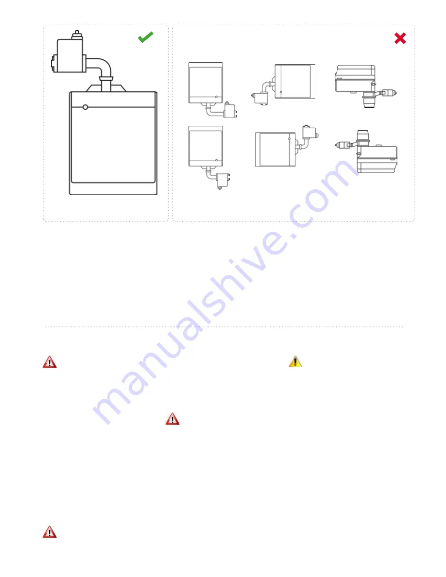
2.9 Burner position
The burner must conform to the local stand-
ards and legislations in place.
The RIELLO-burner has been designed to
operate in the position shown in Figure
11, the positions shown in Figure 12, won't
allow the air damper to close when the
burner is on standby.
Figure 11.
Correct burner position
Figure 12.
Incorrect burner position
2.10 Gas Installation/connection
WARNING
The installation must be purged and tested
for soundness prior to commissioning.
Always ensure that appropriate personal
protective equipment is used
Service pipework must terminate at an
approved isolating valve, and be adjacent
to the position of the heater. The connec-
tion to the heater can be made by way of
either an approved flexible coupling, or
rigid connection. Threaded connections
must comply with ISO288/1 of ISO 7/1,
further information concerning the accepted
practice in European countries is detailed
in EN 1020.
The diameter of the pipework from the
isolating valve to the burner connection
must not be less than the diameter of the
burner connection inlet.
2.11 Oil Installation/connection
WARNING
Prolonged exposure and contact with gas
oil can result in the natural oils being
removed from the skin, sensitisation can result in
dermatitis.
Always ensure that the appropriate personal
protective equipment is used.
2.12 Fuel supply
WARNING
Galvanised or plastic pipe work and fittings
must not be used. (See BS 5410 Part 1)
The constraints of the application will, to a
large extent, determine whether it is prefer-
able to use a single pipe gravity feed system,
or whether the two pipe pumped system is
more appropriate. Where more than one
appliance is to share a common supply it
will be necessary to use a pressurised ring
main system.
All pipe work must be constructed and
installed so that it does not permit the
ingress of air. The construction, size, and
position of the oil storage tank must take
account of the current regulations, as well as
suiting the requirements of the installation.
CAUTION
On pumped systems always check that the
pump is correctly set up prior to operation.
Ensure that valves are open allowing a
free flow of oil through the system.
In order to promote trouble free operating it
is necessary that the oil within the storage
tank and oil line does not fall below the
cold filter plugging point (cfpp), in the UK
and with class D fuel (also referred to as gas
oil). The critical temperature is -4°C for this
summer grade.
The cfpp critical temperature for the winter
grade is -12°C. If summer grade fuel is stored
for winter use in areas prone to severe frosts
and low temperatures it will be necessary
to insulate or even heat the supply tank and
pipe work.
Note:
The fuel supplier should be contacted prior to
installation so that any requirements concerning delivery,
transport, storage and use can be addressed before work
commences.
14


