background image

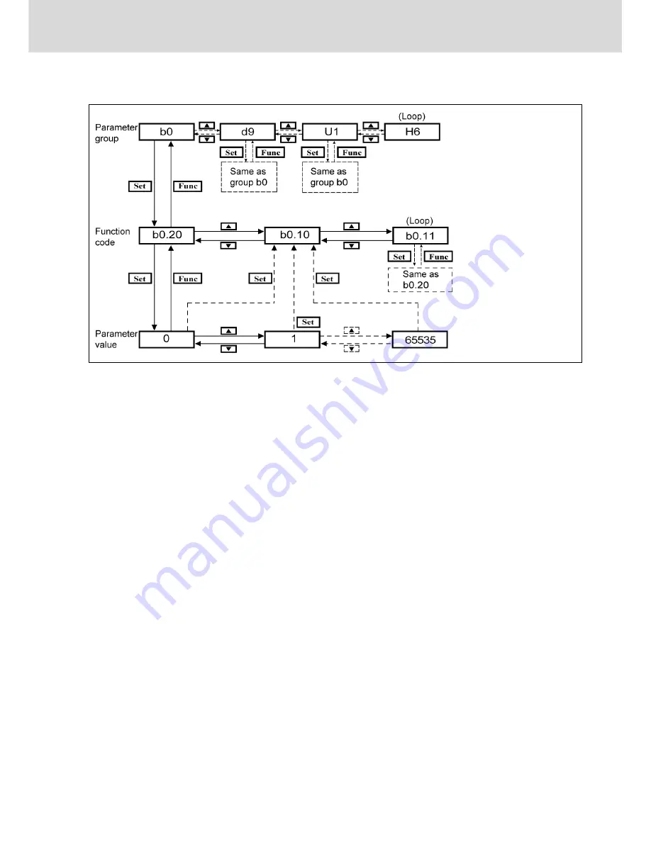
8.1.2  Operating Descriptions

Fig.  8-2:   Operating mode

8.1.3  Fast Access to Parameters with Button Combinations

Brake  chopper  provides  fast  access  to  parameters  within  a  parameter  group

with '<Func> + <▲>' or '<Func> + <▼>' combinations.

Press '<Func> + <▲>' once, the blinking bit move one bit to left.

Press '<Func> + <▼>' once, the blinking bit move one bit to right.

Example:
Change  the  value  of  parameter  b0.20  from  '0'  to  '1000',  perform  the  following

steps.

Step 1: press '<Func> + <▲>' or '<Func> + <▼> to active the fast access func-

tion, '0' is displayed.

Step 2: press '<Func> + <▲>' for three times, move three bits to the left, '0000'

is displayed and the left-most '0' is blinking.

Step 3: press <▲> button to change left-most '0' to '1', then '1000' is displayed

and '1' is blinking.

Step 4: press <Set> button to save the setting. The screen will return to previ-

ous menu and parameter 'b0.10' will be displayed.

Brake Chopper 

Bosch Rexroth AG

Operating Panel and Dust Cover

DOK-RCON03-EFC*BRAKE**-IT01-EN-P

37/65

Содержание EFC x610 Series

Страница 1: ...EFC x610 Series Brake Chopper Operating Instructions R912007235 Edition 01...

Страница 2: ...her information set forth in it are the exclusive property of Bosch Rexroth Xi an Electric Drives and Controls Co Ltd It may not be reproduced or given to third parties without its consent Liability T...

Страница 3: ...gainst Magnetic and Electromagnetic Fields During Op eration and Mounting 10 1 4 5 Protection against contact with hot parts 10 1 4 6 Protection during handling and mounting 11 2 Important Directions...

Страница 4: ...es 28 6 3 Terminals 29 6 3 1 Power Terminals 29 6 3 2 Control Terminals 30 6 3 3 Digital Signal Internal Wiring 32 7 Electromagnetic Compatibility EMC 33 7 1 Cable Connections between Brake Chopper an...

Страница 5: ...Surge Current or Short Circuit 50 10 3 4 Error 05 OH b Brake Chopper Overheat 50 10 3 5 Error 07 OH r Brake Resistor Overheat 51 10 3 6 Error 09 E Par Invalid Parameter Setting 51 10 3 7 Error 10 idE...

Страница 6: ...Page 14 1 2 UL 60 14 1 3 EAC 61 14 1 4 EU RoHS 62 14 2 Appendix II Type Coding 63 Bosch Rexroth AG Table of Contents Brake Chopper IV DOK RCON03 EFC BRAKE IT01 EN P...

Страница 7: ...product with a defined function intended for users and placed on the market as an individual piece of merchandise Electrical Equipment Electrical equipment encompasses all devices used to generate con...

Страница 8: ...components of the electric drive and control system as well as with the haz ards this implies and who possess the qualifications their work requires To comply with these qualifications it is necessary...

Страница 9: ...uction death or serious injury could occur CAUTION In case of non compliance with this safety instruction minor or moderate injury could occur NOTICE In case of non compliance with this safety instruc...

Страница 10: ...ow these safety instructions Bosch Rexroth is not liable for damages resulting from failure to observe the safety instructions Read the operating maintenance and safety instructions in your language b...

Страница 11: ...tion are met The instructions for installation in accordance with EMC requirements can be found in the section on EMC in the respective application documentation The machine or installation manufactur...

Страница 12: ...d for persons with heart pacemakers metal implants and hearing aids in proximity to electric drive systems Risk of burns by hot housing surfaces Risk of injury by improper handling Injury by crushing...

Страница 13: ...nnected to the points of the components provided for this purpose Before accessing electrical parts with voltage potentials higher than 50 V you must disconnect electric components from the mains or f...

Страница 14: ...incorrect connection If extra low voltage circuits of devices containing voltages and circuits of more than 50 volts e g the mains connection are connected to Bosch Rexroth prod ucts the connected ex...

Страница 15: ...nd protective coverings are strong enough to re sist maximum possible kinetic energy Mount emergency stopping switches in the immediate reach of the operator Before commissioning verify that the emerg...

Страница 16: ...ts or metal pieces as well as with hearing aids must consult a doctor before they enter the areas described above 1 4 5 Protection against contact with hot parts Hot surfaces of components of the elec...

Страница 17: ...table equipment for mounting and transport Avoid jamming and crushing by appropriate measures Always use suitable tools Use special tools if specified Use lifting equipment and tools in the correct ma...

Страница 18: ...ardware they must remain in their original state in other words no structural changes are permitted It is not permitted to decompile software products or alter source codes Do not mount damaged or fau...

Страница 19: ...e contact Bosch Rexroth distributor 1 Product series 2 Short text Type code 3 Volume 4 Net weight 5 Material number 6 Product version index 7 Mass weight 8 Production week e g 14W20 means week 20 in 2...

Страница 20: ...plate1 1 Certification Fig 3 3 Product nameplate2 3 2 Visual Inspection Check the product for transport damages e g deformation or loose parts im mediately after unpacking In case of damage contact th...

Страница 21: ...mponents CAUTION Damage to the components caused by long storage periods When storing these components for a long period of time remember to operate them once a year Description Symbol Unit Value Temp...

Страница 22: ...ects the DC bus voltage in real time If the bus voltage reaches the pre set start voltage which can be set by parameter H6 01 brake chopper will start braking during which the electrical energy return...

Страница 23: ...0 m 1 000 4 000 m Relative humidity 90 RH No condensation Degrees of protection IP 20 Degrees of pollution 2 EN 50178 Vibration 10 Hz f 57 Hz amplitude 0 075 mm 57 Hz f 150 Hz acceleration 1 g Mountin...

Страница 24: ...hort circuit protection Terminal Digital input terminal 5 digital input terminals Digital output terminal Digital output terminals OUT OUT one relay output Maximum current continuous brak ing time 0 0...

Страница 25: ...e is 100 the rec ommended brake chopper and brake resistor are listed as below Brake pow er KW Brake chopper type code Number of brake choppers Brake resistence Power of brake resis tor KW Number of p...

Страница 26: ...f the brake chopper The current Ic through the brake resistor can be calculated by formula Ic Ud Rb in which Ud is the braking operating voltage of brake chopper After the adjustment of the resistance...

Страница 27: ...the upper brake chopper if the upper limit of air temperature is exceeded Fig 5 1 Mounting distance and arrangement dhor Distance horizontal 0 mm dtop Minimum top distance 125 mm dbot Minimum bottom...

Страница 28: ...figure 5 2 2 Dimensions Model W H D w h d Screw size Net weight kg FEAE07 1 EA1 NNNN 100 215 149 70 205 140 4 5 M4 2 24 FEAE07 1 EA2 NNNN 2 34 Tab 5 1 Brake chopper dimensions unit mm Bosch Rexroth AG...

Страница 29: ...Brake Chopper Wiring 6 1 System Wiring 6 1 1 Electrical Interface Fig 6 1 Electrical interface of brake chopper Brake Chopper Bosch Rexroth AG Brake Chopper Wiring DOK RCON03 EFC BRAKE IT01 EN P 23 6...

Страница 30: ...cal Connection Mode 1 Fig 6 2 Typical connection mode 1 6 1 3 Typical Connection Mode 2 Fig 6 3 Typical connection mode 2 Bosch Rexroth AG Brake Chopper Wiring Brake Chopper 24 65 DOK RCON03 EFC BRAKE...

Страница 31: ...r Please connect to frequency converter directly or install a termi nal block The master slave control mode of the brake chopper supports the following two connections which currently supports up to t...

Страница 32: ...to the actual application For cable specification for international without USA Canada ONLY USE copper wires of 90 or above with XLPE or EPR insu lation according to IEC60364 5 52 For cable specifica...

Страница 33: ...52 DIN VDE 0298 4 EN 60204 1 2 Recommendation for design of the fuses International except for USA Canada Class gL gG 500 V 690 V design NH D DIAZED or D0 NEOZED Characteristics In the case of error...

Страница 34: ...2 1 1 5 AWG 17 16 Ferrule length mm 10 10 Stripped length mm 10 10 Tab 6 3 Cable requirements Please follow the steps below for wiring of control terminals Step 1 Switch off the brake chopper before p...

Страница 35: ...iption P Mains supply input terminals N PB Output terminals P1 Tab 6 4 Power terminals description Fig 6 6 Grounding and PE terminals 1 Power circuit terminal 2 Control circuit terminal Brake Chopper...

Страница 36: ...ower supply of the brake chopper has been switch ed off before plugging or unplugging the connector The terminal block is ONLY for wiring convenience which CANNOT be used for fixing the cables Additio...

Страница 37: ...ce point isola tion with GND Relay signal terminals Terminal Signal function Description Signal requirement Ta Relay changeover con tacts See parameter H6 10 Rated capacity 250 VAC 3 A 30 VDC 3 A Tc T...

Страница 38: ...ls TG and Reset Terminals Reset and TG are using the switching signals Do not need external power supply Fig 6 9 Wiring of terminals IN and OUT Terminals IN IN OUT and OUT are ONLY used in Master Slav...

Страница 39: ...Cable Connections between Brake Chopper and Frequency Converter Fig 7 1 Cable connections between brake chopper and frequency converter Brake Chopper Bosch Rexroth AG Electromagnetic Compatibility EM...

Страница 40: ...rence free lines as well as to signal cables and signal lines alternatively separated by a grounded distance plate in separate cable ducts if possible Routing the Motor Power Cables and Mains Connecti...

Страница 41: ...ecause they are functioning like reception antennas noise immunity and like transmitting antennas emission of interference Exceptional cases are flexible cable tracks over short distances of a maximum...

Страница 42: ...onal accessory The typecode of LED panel is FPCC02 1 EANN 7P NNNN the firmware version of LED panel is 02V08 and above 2 Run button potentiometer and indicators Run FWD REV are not used in brake chopp...

Страница 43: ...ameter b0 20 from 0 to 1000 perform the following steps Step 1 press Func or Func to active the fast access func tion 0 is displayed Step 2 press Func for three times move three bits to the left 0000...

Страница 44: ...l type setting range Press Func button and do not release it until or button has been pressed Press or button within 2 s if Func button is pressed If Func button is pressed and no other buttons be pre...

Страница 45: ...nd group code 2 Set the parameter value 2 Func button Enter the parameter group screen and go back to previous screens 3 Text area Used for displaying 1 Parameter monitoring screen 2 Parameter group P...

Страница 46: ...de or Pressing Func button with Loc button for longer than 3 s Stop button is used to reset error Run button is not used in brake chopper 8 2 2 Operating Example Please follow the steps below to set p...

Страница 47: ...fied bx xx Hx xx Ux xx dx xx Function parameter values 9 1 2 Parameter List Code Name Setting range Default Min Attri b0 10 Parameter initialization 0 Inactive 1 Restore to default settings 2 Clear er...

Страница 48: ...last error type Read H6 52 Third last error type Read H6 53 DC bus voltage at last error 1 Read H6 54 Braking current at last error 0 1 Read H6 55 Power module temperature at last error 1 Read d9 00...

Страница 49: ...ake chopper and then replicate its settings for all the other brake choppers Code Name Setting range Default Min Attri b0 11 Parameter copy 0 2 0 Stop 0 Inactive This parameter will be reset to 0 Inac...

Страница 50: ...mode is set by inputting function code directly via the panel not via the jumper cap or pin Code Name Setting range Default Min Attri H6 00 Brake chopper mode 0 Standalone 1 Master 2 Master slave 3 S...

Страница 51: ...Set the braking start voltage according to the actual situations The default value of EFC model is set to 750 V Brake chopper starts running at the pre set start voltage and shuts down with a hystere...

Страница 52: ...r is reset 1 Brake chopper working The output is active when the brake chopper is running 2 Brake chopper ready After powering on if no error occurs and not being in braking state brake chopper is rea...

Страница 53: ...51 Second last error type Read H6 52 Third last error type Read H6 53 DC bus voltage at last error 1 Read H6 54 Braking current at last error 0 1 Read H6 55 Power module temperature at last error 1 Re...

Страница 54: ...connected to terminals IN of the slave For example when three brake choppers are connected in parallel terminals OUT of brake chopper 1 connect to termi nals IN of brake chopper 2 and terminals OUT o...

Страница 55: ...ode Code Description During parameter backup 10 2 Warning Code Code Description S Err Parameter change blocked PrSE Parameter setting contradiction Brake Chopper Bosch Rexroth AG Diagnosis DOK RCON03...

Страница 56: ...ke resistor The power of brake chopper is too small Choose brake chopper with proper power 10 3 3 Error 03 SC Surge Current or Short Circuit Possible reason Solution Earth surge Remove the short circu...

Страница 57: ...tem perature sensor of brake resistor Adjust threshold of temperature sensor of brake resistor Inappropriate setting for duty cycle of brake chopper Reduce the duty cycle accordingly 10 3 6 Error 09...

Страница 58: ...the device must be disconnected from the mains voltage Ensure that the mains voltage is not reconnected 11 2 Daily Inspection Please conduct daily inspection as indicated in the table below in order t...

Страница 59: ...le line No loose connection Tighten crimp and terminal screw Crimp terminal and terminal block Brake chopper Visual appearance No deformation Contact with service Fan No color change or deformation Re...

Страница 60: ...above figure Step 2 Hold dust cover and pull it out horizontally from the mounting plate Remove the dust cover when use the brake chopper for the first time install an operating panel to set the relat...

Страница 61: ...FEAE07 1 EA2 NNNN is equipped with fan units Step 1 Unscrew the two screws on the fan cover Step 2 Take off the fan cover Step 3 Slowly remove the fan Step 4 Disconnect fan power wires Brake Chopper...

Страница 62: ...ional information on service repair e g delivery addresses and training can be found on our internet sites Service worldwide Outside Germany please contact your local service office first For hotline...

Страница 63: ...er synthetic materials brass electronic components and modules magnetic materials electronic components and modules 13 2 Disposal Return of products Our products can be returned to our premises free o...

Страница 64: ...tors contained in Rexroth products have to be properly disposed of according to the country specific collection Recycling Most of the products can be recycled due to their high content of metal In ord...

Страница 65: ...ales representative for the declarations of conformity EU directives Standards Low Voltage Directive 2014 35 EU EN 61800 5 1 IEC 61800 5 1 2007 EMC Directive 2014 30 EU EN 61800 3 IEC 61800 3 2004 A1...

Страница 66: ...XIAN ELECTRIC DRIVES AND CONTROLS CO LTD Category name Power Conversion Equipment File number E328841 UL ratings For using the components in the scope of UL take the UL ratings of the individu al com...

Страница 67: ...llowing features Surge protective devices device shall be a Listed Surge protective device Category code VZCA and VZCA7 Rated nominal voltage 480 277 VAC 50 60 Hz 3 phase Clamping voltage VPR 2 000 V...

Страница 68: ...t of RoHS Restriction on the use of certain Hazardous Substances directive 2011 65 EU with the exemption per Annex of 2011 65 EU EU RoHS marking Fig 14 4 EU RoHS marking Bosch Rexroth AG Appendix Brak...

Страница 69: ...14 2 Appendix II Type Coding Fig 14 5 Brake chopper type coding Fig 14 6 Operating panel type coding Brake Chopper Bosch Rexroth AG Appendix DOK RCON03 EFC BRAKE IT01 EN P 63 65...

Страница 70: ...Bosch Rexroth AG Brake Chopper 64 65 DOK RCON03 EFC BRAKE IT01 EN P...

Страница 71: ...Notes Brake Chopper Bosch Rexroth AG...

Страница 72: ...rols Co Ltd No 3999 Shangji Road Economic and Technological Development Zone 710021 Xi an P R China Phone 49 9352 40 5060 Fax 49 9352 18 4941 service svc boschrexroth de www boschrexroth com R91200723...

Отзывы: