


6
www.restek.com
2.5
Instrument Installation
2.5.1
Mobile Phase Reservoirs
The mobile phase reservoir should be placed at the same level or slightly higher than the pump, never below the pump, and the
inlet tubing should be as short as practical. These steps minimize pressure losses on the inlet side of the pump during refill and
help to avoid bubble formation. These steps are particularly important when using high vapor pressure solvents (hexane, methy-
lene chloride, etc.). Mobile phases should be degassed, filtered, and covered. (See Section 2.4.)
2.5.2
Inlet Tubing and Filters
All inlet lines are supplied in a 36" (91 cm) length, with a 0.085" ID and a
1
/
8
" OD, and are made of a PTFE-based material. Use a
20 micron slip-on inlet filter.
2.5.3
Outlet Tubing
Outlet tubing is not supplied with the pump. It should be
1
/
16
" OD, type 316 stainless steel. Tubing with a 0.020" ID normally is
used before the injection valve. Tubing with a 0.010" inner diameter normally is used after the injection valve. The tubing must be
cut squarely, with no burrs. It should not be crimped and the center hole must be open.
2.5.4
Priming the Pump
Be sure all of the connections downstream of the prime/purge valve are closed. Connect a syringe to the prime/purge valve. Open
the prime/purge valve 1 to 2 turns counter-clockwise. Run the pump at a flow rate of 3 to 5 mL/min. Prime the pump by pulling
mobile phase and any air bubbles through the system and into the syringe (a minimum of 20 mL). Close the prime/purge valve
and stop the pump.
2.5.5 Long Term Pressure Calibration Accuracy
This note applies if your pump is equipped with an electronic pressure transducer. The transducer has been zeroed and calibrated
at the factory. Over the life of the pump, some drift may occur. For example, it is typical for the zero to drift < 10 psi after about 1
year of operation (i.e., with no back pressure on the pump a reading of 1-9 psi may be displayed). A similar drift may also occur at
higher pressures, and are typically less than 1% (e.g. <50 psi at 6,000 psi back pressure).
If pressure calibration and/or drift are a concern, consult the factory. The pump can be shipped back to Restek for recalibration.
Alternatively, written calibration and zero-reset procedures are available. Consult Restek to receive these instructions.
2.6
Preparation for Storage or Shipping
2.6.1
Isopropanol Flush
Disconnect the outlet tubing from the pump. Insert the inlet filter in isopropanol. Open the prime/purge valve and use a syringe
to draw a minimum of 50 mL. Close the prime/purge valve and pump a minimum of 5 mL of isopropanol to exit. Leave the inlet
tubing connected to the pump. Place the inlet filter in a small plastic bag and attach it to the tubing with a rubber band. Plug the
outlet port with the shipping plug, leave a length of outlet tubing on the pump, or cover the outlet port with plastic film.
2.6.2
Packaging for Shipping
CAUTION: Re-package in the original carton, if possible. If the original carton is not available, wrap the pump in several layers of
bubble wrap and cushion the bottom, top, and all four sides with 2" of packaging foam. An HPLC pump is a delicate instrument
and must be carefully packaged to withstand the shocks and vibration of shipment.
3.
Operation
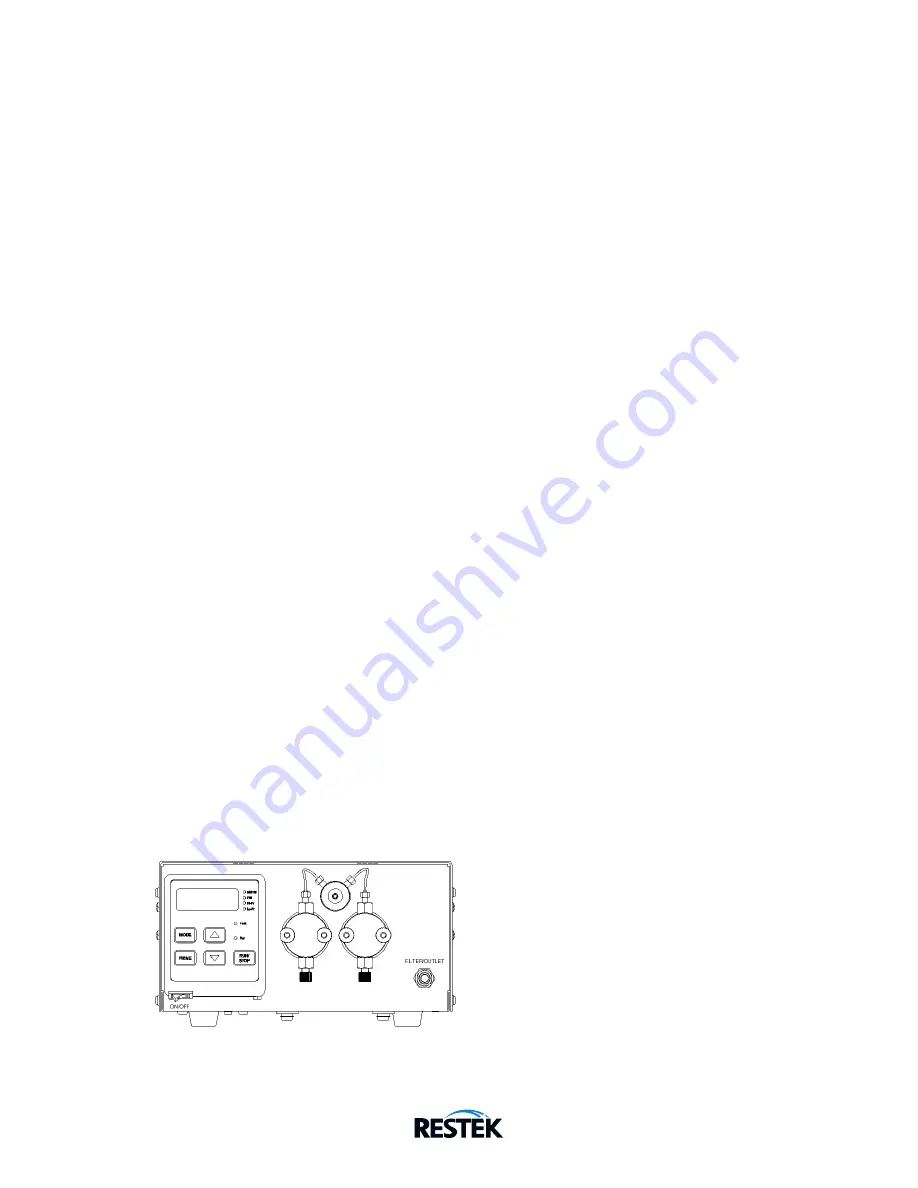
3.1
Front Panel Controls and Indicators
Figure 3-1. Dual Head Pump Front Panel


