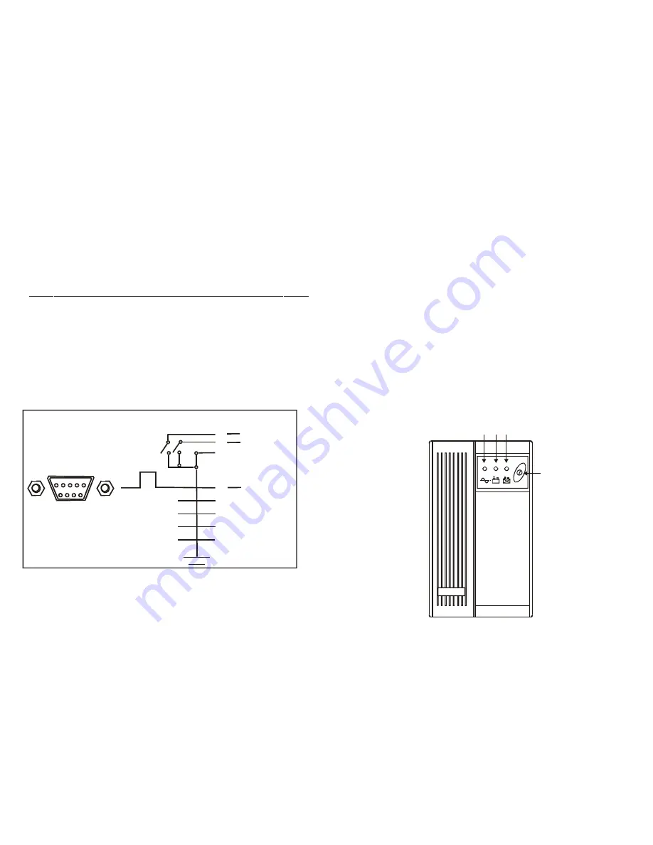
COMPUTER INTERFACE
The computer interface (DB9 port) on the back of the UPS may be
connected to a host computer. This port allows the computer to monitor the
status of the UPS and control the operation of the UPS.
Pin out information:
PIN# Description I/O
Output
Input
Input
Output
PIN1
PIN2
PIN3
PIN4
PIN5
PIN6
PIN7
PIN8
PIN9
Battery low, normally open, active close
N.C.
Common Ground
Remote shut down, keep this pin high
(+5~+12V) for 3S will turn off the UPS
N.C.
N.C.
Must keep in high state
Line fail, normally open, active close
N.C.
1
2
3
4
5
6
7
8
9
D-SUB 9 Pin Female Connector
Signal High Min. 3 Second
Contacts
Normally
Open
Low Battery
Mains Failure
Pin Number
UPS Shut Down
5
8
6
3
1
4
7
2
9
- 8 -
OVERVIEW
Front Panel
1.
Master Power Switch:
Turn on/off the UPS.
2.
Green LED:
AC Normal .
3.
Yellow LED:
Battery in back-up
4.
Red LED:
UPS Cut-off
Rear Panel
1.
Input:
IEC type connector to connect the power cable.
2.
AC Fuse:
Protection against short-circuits electronic fuse.
3.
Data line protection:
Filtering of electrical noise on data transmission
lines.
4.
Communication port:
Basic communications.
5.
AC/Battery outputs:
Output protected for critical loads that require
additional electrical power
6.
UPS function setup:
No load auto-shut down, Dc-start On and Buzzer
Alarm auto-reset.
7.
USB PORT (OPTION)
Picture:
1
2 3 4
- 5 -


