background image

APPENDIX B

 – 

Advanced Gate Controller Configurations


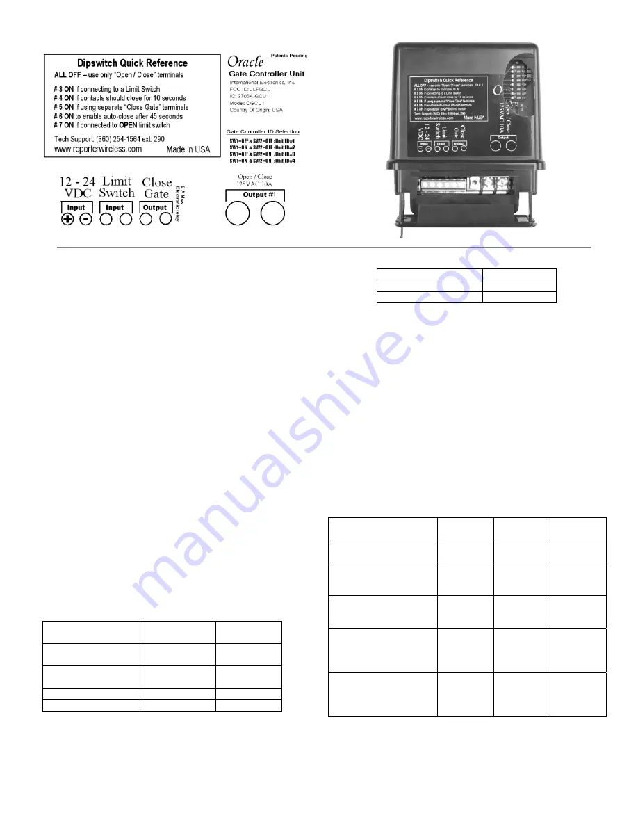
From left to right, Gate Controller Terminals are: 

− 

− 

− 

− 

− 

− 

− 

− 

Optional power input.  +9Vto +24VDC.  Make sure that 
your gate’s DC power supply “Ground” is wired to 
terminal 2.  


Ground or Common terminal.  


Limit switch input A.  Wire such that when the limit 

switch is closed, terminal 4 is shorted to terminal 3.  


Limit switch input B.  Wire such that when the limit 
switch is closed, terminal 4 is shorted to terminal 3.   


Secondary Relay Contact A.  Up to 120VAC LOW 
CURRENT contact.  Max ½ amp.  Typically wired to 
optional “Close Gate” input on Automatic Gate Opener.  


Secondary Relay Contact B.  Up to 120VAC LOW 
CURRENT contact.  Max ½ amp.  Typically wired to 
optional “Close Gate” input on Automatic Gate Opener.  


Primary Relay Contact A.  Up to 120VAC.  Max 10 amps.  
Typically wired to “Open Gate”, “Open/Close” or 
“Remote” input on Automatic Gate Opener.  


Primary Relay Contact B.  Up to 120VAC.  Max 10 amps.  
Typically wired to “Open Gate”, “Open/Close” or 
“Remote” input on Automatic Gate Opener. 


Selecting Gate Controller “ON” Time 

For most connections to an Automatic Gate Opener, the 
default setting of ½ second is best.  However, for 

connection to yard lights, cameras, etc., you may wish 
to adjust how long the connected device stays on. 


Gate Controller 
“ON” Time 

Dipswitch 

#3 

Dipswitch 

#4 

½ second –  
No Limit Switch  

OFF OFF 

½ second –  
Using a Limit Switch 

ON OFF 

10 seconds 

OFF 

ON 

30 seconds 

ON 

ON 


NOTE: 

For most gate system wiring, 

dipswitch #4 should be left “OFF.”  If 
you wire your gate controller to a 

limit switch, dipswitch #3 should be 
turned “ON”.  


Enabling the Auto-Close Feature 

Auto-Close Feature 

Dipswitch #6 

OFF (disabled) 

OFF 

ON (enabled) 

ON 


By enabling the Auto-Close feature, the Gate Controller 
will attempt to close the gate 45 seconds after it is 

opened.  This feature will work better if your 
configuration has at least one of the following elements: 


Separate Open / Close Terminals, 

A “Gate Closed” Sensor or limit switch, or 
A “Gate Open” Sensor or limit switch 


Otherwise, the Gate Controller must assume that the 
gate has not opened or closed for any other device. 


Warning:


Please remember safety!  Do not enable 

auto-close where it might pose a risk 

of entrapment, causing injury, death, 
or damage to vehicles


Using Additional Contact / Clearance Sensors 


NOTE: 

To power an additional contact sensor that is 

NOT already connected to your gate system, 
short terminal #3 to ground, connects the 

switch across terminals 3 and 4, and turn 
dipswitch #8 ON.   

Open/Closed Contact 
Sensors 

Dipswitch

#3 

Dipswitch

#7 

Dipswitch

#8 

No contact sensors 
used  

OFF OFF OFF 

“Closed” limit switch 

wired to terminals #3 
and #4 


ON 


OFF 


OFF 

“Open” limit switch 
wired to terminals   #3 
and #4 


ON 


ON 


OFF 

Additional “Closed” 
limit switch or sensor 
wired to terminals #3 
and #4 


ON 


OFF 


ON 

Additional “Open” 
limit switch or sensor 
wired to terminals #3 
and #4 


ON 


ON 


ON 

Содержание Oracle 3000

Страница 1: ... 1 Activating the Gate Access Unit 1 Activating Oracle Accessories Activating a new Gate Control Unit 1 Activating Key fob Remotes 1 Activating Intercoms and Accessories 1 Gate Control Unit GCU Installation Basic Gate Controller Installation 2 Setting the Gate Controller ID 1 2 2 General Operation Intercom Function 2 Opening and Closing a Gate Oracle System Intercom Settings Intercom Gate Status D...

Страница 2: ...u only have one Gate Controller enter an ID of 1 Repeat the process for any additional Gate Controllers setting their ID as above Example Enter M M M M 1 MMMM is the sample Master PIN 1 selects the 1 Gate Controller Activating Key Fob Remotes Each numbered button on a remote must be activated separately to control one of four Gate Controllers Enter your master PIN number on the Gate Access Panel f...

Страница 3: ...om units will beep and the TALK REMOTE buttons or ACTIVE light will illuminate The intercom will continue to beep for 40 seconds During this time the Intercom will ONLY connect to that Gate Access Panel Hold down the TALK button to speak to the visitor Release the TALK button to hear the response This will be a secure conversation and other Intercoms will be locked out Opening and Closing a Gate T...

Страница 4: ...ith limited function See Multi GAP Mode sw1 is ON for Master Mode used by itself with no GAP and OFF to be used with a Gate Access Panel sw2 in Multi GAP mode the ON position will activate Gate Controller 2 and OFF activates GCU 3 See Multi GAP Mode 1 2 3 4 PIN CODES User Level PIN Codes The gate system can support up to 50 PIN numbers for other users To add an additional PIN enter your Master PIN...

Страница 5: ... been taught to the slaved GAP will have to have their memory cleared and be re taught to the system as if they where newly installed units Enter the Master PIN followed by 5 5 then enter 1 2 or 3 to select the new operating channel group The Gate Access Panel will give a single beep Channel group 1 is the default setting Example Enter M M M M 5 5 3 MMMM is the sample Master PIN 55 enters Channel ...

Страница 6: ...M M 0 5 MMMM is the Master PIN 05 enters LEARN mode for one minute to activate a new Intercom or other accessory Activating a Key Fob Remote M M M M 8 1 2 1 4 LEARN MMMM is the Master PIN 8 enters Activate Remote mode and 1 selects the 1 Gate Controller the last digit is the 1 button on the emote Adding Additional USER level PIN Codes M M M M 9 P P P P n MMMM is the Master PIN 9 enters Adding a Ne...

Страница 7: ... OFF OFF second Using a Limit Switch ON OFF 10 seconds OFF ON 30 seconds ON ON NOTE For most gate system wiring dipswitch 4 should be left OFF If you wire your gate controller to a limit switch dipswitch 3 should be turned ON Enabling the Auto Close Feature Auto Close Feature Dipswitch 6 OFF disabled OFF ON enabled ON By enabling the Auto Close feature the Gate Controller will attempt to close the...

Страница 8: ...tation connect Contacts 5 and 6 to the Close contacts Slide Gate Controller Dipswitch 5 to the UP position If desired enable Auto close on the Gate Controller by flipping Gate Controller Dipswitch 6 to the UP position Sample Configuration 3 Open Close Gate and Verify Gate Status Use this configuration when you wish to use the Reporter Gate System to open and close your gate and check the gate s ac...

Страница 9: ...e GCU may be out of range If the units work properly when close together the GCU may need to be mounted higher off the ground or on a different surface Metal trees or masonry cause the most interference If the units do not work when close together the GAP or MiniGate has not mated with that GCU Double check the GCU s ID as set with dipswitches 1 2 and re teach it My Oracle System Network has very ...

Отзывы: