


3
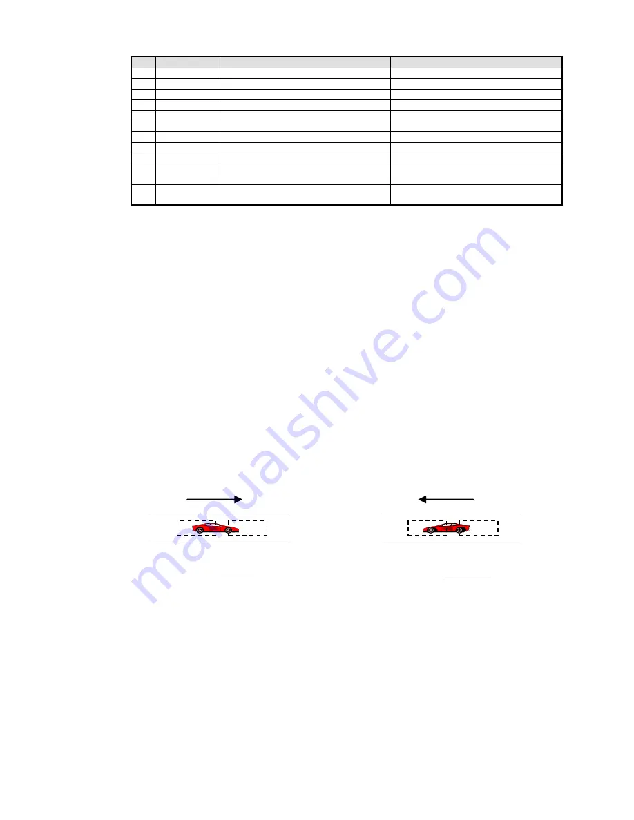
CH 1 LOOP
CH 2 LOOP
BA Direction
CH 1 LOOP
CH 2 LOOP
AB Direction
VI
Pin Connections
Two Connector (2C) Models - Requires Two (2) Reno A & E Harnesses (Model 802-4)
Pin
Wire Color
Function (Connector 1)
Function (Connector 2)
1
Black
AC Line / DC +
No Connection
2
White
AC Neutral / DC Common
No Connection
3
Orange
Channel 1 Presence Relay, Normally Open (N.O.)
Channel 2 Presence Relay, Normally Open (N.O.)
4
Green
No Connection
No Connection
5
Yellow
BA Relay, Common
AB Relay, Common
6
Blue
BA Relay, Normally Open (N.O.)
AB Relay, Normally Open (N.O.)
7
Gray
Channel 1 Loop
Channel 2 Loop
8
Brown
Channel 1 Loop
Channel 2 Loop
9
Red
Channel 1 Presence Relay, Common
Channel 1 Presence Relay, Common
10
Violet, or
Black / White
BA Relay, Normally Closed (N.C.)
AB Relay, Normally Closed (N.C.)
11
White / Green or
Red / White
Channel 1 Presence Relay, Normally Closed (N.C.) Channel 2 Presence Relay, Normally Closed (N.C.)
NOTE: All pin connections listed above are with power applied, loops connected, and no vehicle detected.
VII
Warnings
Separately, for each loop, a twisted pair should be created consisting of only two (2) loop wires running the entire
distance from the loop to the detector (including runs through all wiring harnesses) at a minimum of six (6)
complete twists per foot. For trouble free operation, it is
highly recommended
that
all
connections (
including
crimped connectors
) be soldered.
VIII Directional Logic
The Model AX2DL’s directional logic feature uses the Channel 1 and Channel 2 loops to determine the direction a
vehicle is traveling. The loops must spaced such that the vehicle can span both loops. The expected installation is
two loops, one after the other in the same lane, spaced anywhere from overlapping to 6 feet apart.
NOTE:
Contact a Field Engineer at Reno A & E regarding loop configurations and loop spacing for specific
applications.
When a vehicle enters the first channel’s loop detection area, that channel’s
DETECT
LED will flash at a rate of
750 milliseconds ON and 250 milliseconds OFF to indicate the presence of the vehicle. This flash rate will
continue until the vehicle is clear of the first channel’s loop detection area.
If the second channel’s output is set to Presence mode, its relay will activate and its
DETECT
LED will turn ON as
soon the vehicle enters the second channel’s loop detection area. The relay will remain activated and the DETECT
LED will remain ON until the vehicle is clear of the second channel’s loop detection area.
If the second channel’s output is set to Pulse mode, its relay will momentarily activate (i.e. generate a 250
millisecond pulse) and its
DETECT
LED will flash at a rate of 250 ms ON and 750 ms OFF to indicate the
vehicle’s presence over the second channel’s loop detection area. This flash rate will continue until the vehicle is
clear of the second channel’s loop detection area.
If the vehicle moves out of the first channel’s loop detection area before entering the second channel’s loop
detection area, directional logic detection is aborted and the second channel’s relay and
DETECT
LED will not
activate.
When a vehicle travels from the CH 1 Loop and
enters the CH 2 Loop, the CH 2 Relay and LED
activate to indicate the AB direction.
When a vehicle travels from the CH 2 Loop and
enters the CH 1 Loop, the CH 1 Relay and LED
activate to indicate the BA direction.


