• The extraction box is not suitable for use in
conjunction with blasting units.
• Improper use of grinding tools in the extraction
box carries with it the potential risk of eye and
skin injuries.
• Never grind in the direction of your eyes or
uncovered areas of skin!
• Never work with the viewing pane open!
• Always wear appropriate eye protection
when operating the unit! Failure to wear eye
protection can result in eye injuries due to
airborne particles.
• Always disconnect the unit from the mains
power supply prior to replacing the fluorescent
tube.
• Never press on or bend the lamp body during
replacement (breakage risk). If necessary, wear
gloves or use a cloth.
• Always inspect the electric input lines prior to
operation. Units with damaged input lines may
not be operated.
3.3 Liability Exclusion
Renfert GmbH shall be absolved from all claims for
damages or warranty if:
• The product is employed for any purposes
other than those cited in the operating
instructions;
• The product is altered in any way other than
those alterations described in the operating
instructions;
• The product is repaired by other than an
authorized facility or if any but Renfert OEM
parts are employed;
• The product continues to be employed, despite
obvious safety faults or damage;
• The product is subjected to mechanical
impacts or is dropped.
4. Installation / Commissioning
Prior to connecting the unit to the mains
power supply, compare the information
on the extraction box nameplate with the
specifications of the local mains power
network.
4.1 Setting Up the Unit and Connecting it to
an Extractor
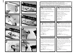
Connect the extraction hose to the extraction tube
(Figure 1).
4.2 Installing the Fluorescent Lamp
Never press on or bend the lamp body du-
ring replacement (breakage risk). If neces-
sary, wear gloves or use a cloth.
1. Insert the fluorescent lamp horizontally (Figure 2).
2. Remove the foil strips from either side of the lamp
cover (Figure 3).
3. Plug the lamp cover in (Figure 4).
4. Install and tighten the knurled nuts (Figure 5).
4.3 Commissioning
1. Connect one end of the power cord to the extrac-
tion box (Figure 6) and plug the other end into the
wall outlet (Figure 7).
2. Switch the unit on (Figure 8).
Your extraction box is now ready for use.
4.4 Installing the Extraction Duct
(applies only to the Dustex master)
With the aid of the extraction duct kit (please refer to
the accessories list), a
Dustex master
can be upgra-
ded to a
Dustex master plus
.
The following retrofit tasks are required in order to
do this:
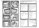
• Remove the base grate (Figure 9).
• Push the extraction duct towards the back so
that the connecting piece in the opening engages
on the rear wall.
• Press the front of the extraction duct onto the ball
pins, making sure it snaps in place (Figure 10).
4.5 Reversing the View Pane
The view pane has a plastic coating on one side.
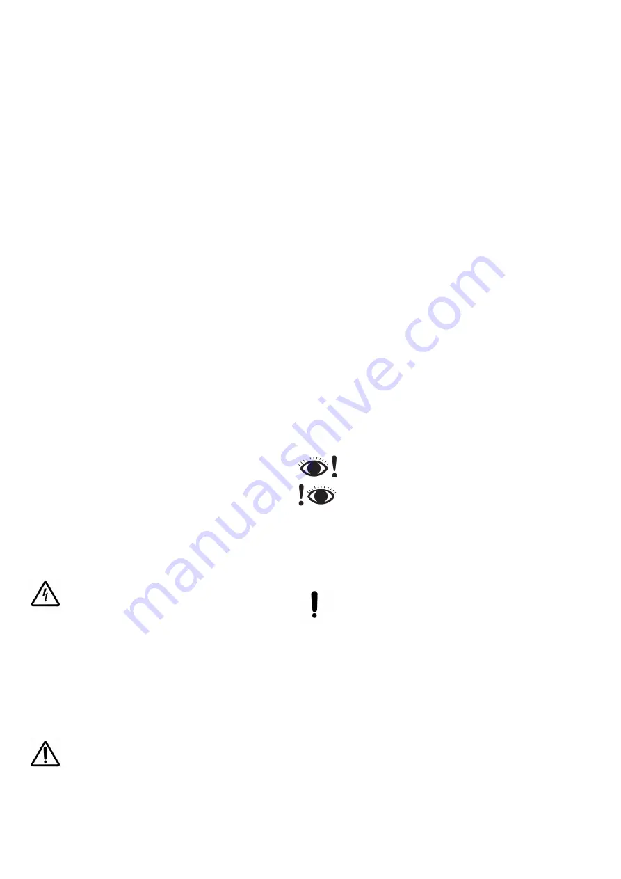
The eye protection symbol provides you with an
indication as to which side of the pane faces inwards:
on the left
>>> Coated side inwards
(Figure 11)
on the right
>>> Glass side inwards
(Figure 12)
This coating is particularly resistant to the abrasive
particles and dust generated during grinding.
However, when grinding and milling components
containing acrylics, electrostatic charges may cause
dust and particles to adhere to the coating.
Polishing agents containing solvents may
also damage the coating.
In such cases, the viewing pane can be reversed so
that the uncoated side faces inwards.
The following steps are required in order to do this:
1. Loosen the screws (Figure 13).
2. Pull the pane out (Figure 14).
3. Reverse the pane.
4. Reinsert the pane (Figure 14).
5. Retighten the screws (Figure 13).
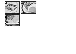
4.6 Armrests (Figure 15)
Armrests can be installed on the
Dustex master
(
plus
) to help relieve strain during work with the unit
(please refer to the accessories list).
Installation instructions are provided with the arm-
rests.
Содержание 26260000
Страница 4: ...17 18 19 ...
Страница 37: ......
Страница 38: ......
Страница 39: ......
Страница 40: ......


