DOC-01011 Rev. A
PAir Extraction System
Installation and User Manual
Страница 1: ...DOC 01011 Rev A ProAero Air Extraction System Installation and User Manual ...
Страница 2: ...tion with the furnishing performance or use of this material Stratasys makes no warranty of any kind with regard to this material including but not limited to the implied warranties of merchantability and fitness for a particular purpose It is the responsibility of the system owner material buyer to determine that Stratasys material is safe lawful and technically suitable for the intended applicat...
Страница 3: ...lter Selection 3 Warning and Information Labels 4 Preparation 4 Installation 5 Connecting to the Power Supply 5 Connecting to the 3D Printer 6 Connecting the Silencer Optional 7 Operation 8 Setting the Desired Airflow 8 Maintenance 8 Inspecting the System 9 Cleaning the System 9 Replacing the Filters 9 Disposing of the Filters 10 System Specifications 11 Dimensions 11 Filter Information 12 ...
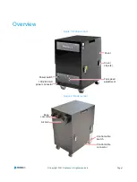
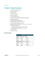
Страница 4: ...asys All rights reserved Overview Figure 1 ProAero front Figure 2 ProAero rear Cover Cover clips 4 Fan speed adjustment Power switch 100 240 VAC power connector Air inlet Keep covered Control cable connector Control cable switch ...
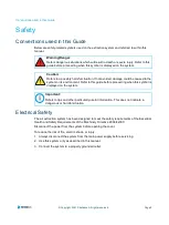
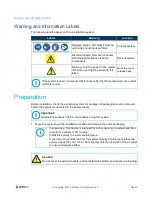
Страница 5: ...lectric shock or injury 1 Always disconnect the system from the mainpower supply before servicing 2 Use this system only as described in this manual 3 Connect the system to a properly grounded outlet Warning Danger Refers dangerous situations which will result in death or severe injury Refer to this guide before proceeding when this symbol is displayed on the system Caution Refers to a possibly ha...
Страница 6: ...itates and releases some of these particulates to the surroundings enabling them to enter the respiratory system and eyes of the operator Additionally depending on the materials used the particulate might irritate the skin Filter Selection The media within the filter in the air extraction system is capable of adsorbing a wide range of organic compounds However it is the responsibility of the user ...
Страница 7: ...es electrical components Back of system Warning Turn the power to the system off before opening the panel with this label Near the cover release clips If the system is used in a manner that is not specified by the manufacturer the system warranty is void Important Read all instructions in this manual before using this system Intended use This device is intended for indoor use only to extract and f...
Страница 8: ... system The power cable should be routed so as not to create a trip hazard Connect the power cable to the system Only connect the cable to the power outlet after finishing the installation process Warning Electric Shock Hazard The extraction system must be connected to a properly grounded outlet Important Check the integrity of the electrical power cable If the power cable is damaged do not connec...
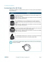
Страница 9: ...t the additional adapter onto the other end of the duct and connect it to the printer exhaust outlet Note Secure the metal bands after connecting Do not remove the 2 smaller caps on the back of the ProAero For all J7 series printers and J835 J850 printers insert this onto the other end of the duct and connect it to the printer exhaust outlet Note Secure the metal bands after connecting Do not remo...
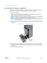
Страница 10: ... 2 Place the silencer on the floor behind the system with the lower part of the silencer facing the system Figure 3 Silencer positioned behind system 3 Either push the silencer forward so it moves under the system or roll the system straight back until it covers the lower part of the silencer completely and is touching the higher part of the silencer 4 Lock the front wheels of the system It is dif...
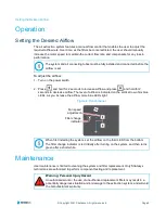
Страница 11: ...lue LEDs As you increase the airflow more blue LEDs light Figure 4 Control panel Maintenance User maintenance is limited to cleaning the system and filter replacement Only Stratasys technicians are authorized to perform component testing and replacement The system and all connecting tubes must be fully installed and connected before the airflow is set When first installing the system set the airfl...
Страница 12: ...he system Replacing the Filters To maintain performance it is important that you replace the filters with identical replacement filters To re order refer to the filter number printed on the filter installed in your extraction system Caution Do not use an abrasive cleaning product as this will damage the finish The ProAero contains a single combined filter Caution To prevent overheating do not use ...
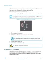
Страница 13: ...ower switch 2 Open the clips on the sides of the system andremove the cover 3 Lift the filter out of the system 4 Insert the new filter into position 5 Replace the cover and fasten the clips Disposing of the Filters The combined filter is manufactured from non toxic materials Filters are not re usable The method of disposal of the used filters depends on the material deposited on them It is the cu...
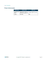
Страница 14: ...mum altitude 2000 m 6561 ft Allowable voltage input fluctuation 10 Control cable 22 48 VDC input 20 mA Operating temperature range 5 C to 40 C 41 F to 104 F Operating humidity range Max 80 Relative Humidity up to 31 C 88 F Max 50 Relative Humidity at 40 C 104 F Pollution degree 2 Intended use Indoor Dimensions Metric mm Imperial inches Crate Weight 72 kg 159 lbs Height 1180 46 5 Width 670 26 4 Dep...
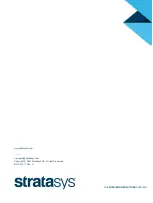
Страница 15: ...tion Page 12 Copyright 2021 Stratasys All rights reserved Filter Information Filter Type Construction Efficiency Combined Filter HEPA Maxipleat Construction with Webbing Spacers 99 997 0 3 microns Carbon Granules NA ...
Страница 16: ...THE 3D PRINTING SOLUTIONS COMPANY www stratasys com _____ c support stratasys com Copyright 2021 Stratasys Ltd All rights reserved DOC 01011 Rev A ...