


M306V8T-EPB User’s Manual
2. Setup
REJ10J0777-0100 Rev.1.00 2005.08.01
Page 38 of 90
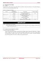
2.11 Selecting Clock Supply
2.11.1 Clocks
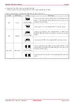
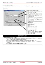
You can choose a clock supplied to the evaluation MCU by the Emulator tab in the Init dialog box of the emulator debugger.
Table 2.4 shows the clocks and their initial settings.
Table 2.4 Clock supply to the MCU
Clock
Display of
emulator debugger
Description Default
setting
Internal
Internal oscillator circuit board
(OSC-3 or OSC-2)
Yes
External
Oscillator circuit on the user system
-
Main (X
IN
-X
OUT
)
Generate
Internal generator circuit
(1.0--16.0 MHz)
-
Internal
Internal oscillator circuit
(32.768 kHz)
-
Sub (X
CIN
-X
COUT
)
External
Oscillator circuit on the user system
Yes
IMPORTANT
Notes on Changing the Clock Supply:
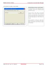
The clock supply can be set by the Init dialog box when starting up the emulator debugger or inputting CLK
command on the script window.
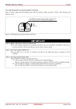
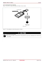
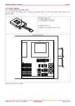
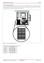
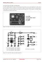
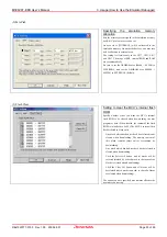
2.11.2 Using an Internal Oscillator Circuit Board
(1) Kinds of Oscillator Circuit Boards
The PC7501 comes with an oscillator circuit board OSC-3 (30 MHz). And an oscillator circuit board OSC-3 (16 MHz)
and an oscillator circuit board OSC-2 (bare board) are included with this product. If you use the internal oscillator
circuit board OSC-3 (16 MHz) or OSC-2 of the PC7501 as a main clock, choose "Internal" in the emulator debugger
after replacing oscillator circuit boards to change a clock supplied to an MCU.
Содержание Emulation Probe M306V8T-EPB
Страница 90: ...M306V8T EPB User s Manual...


