19
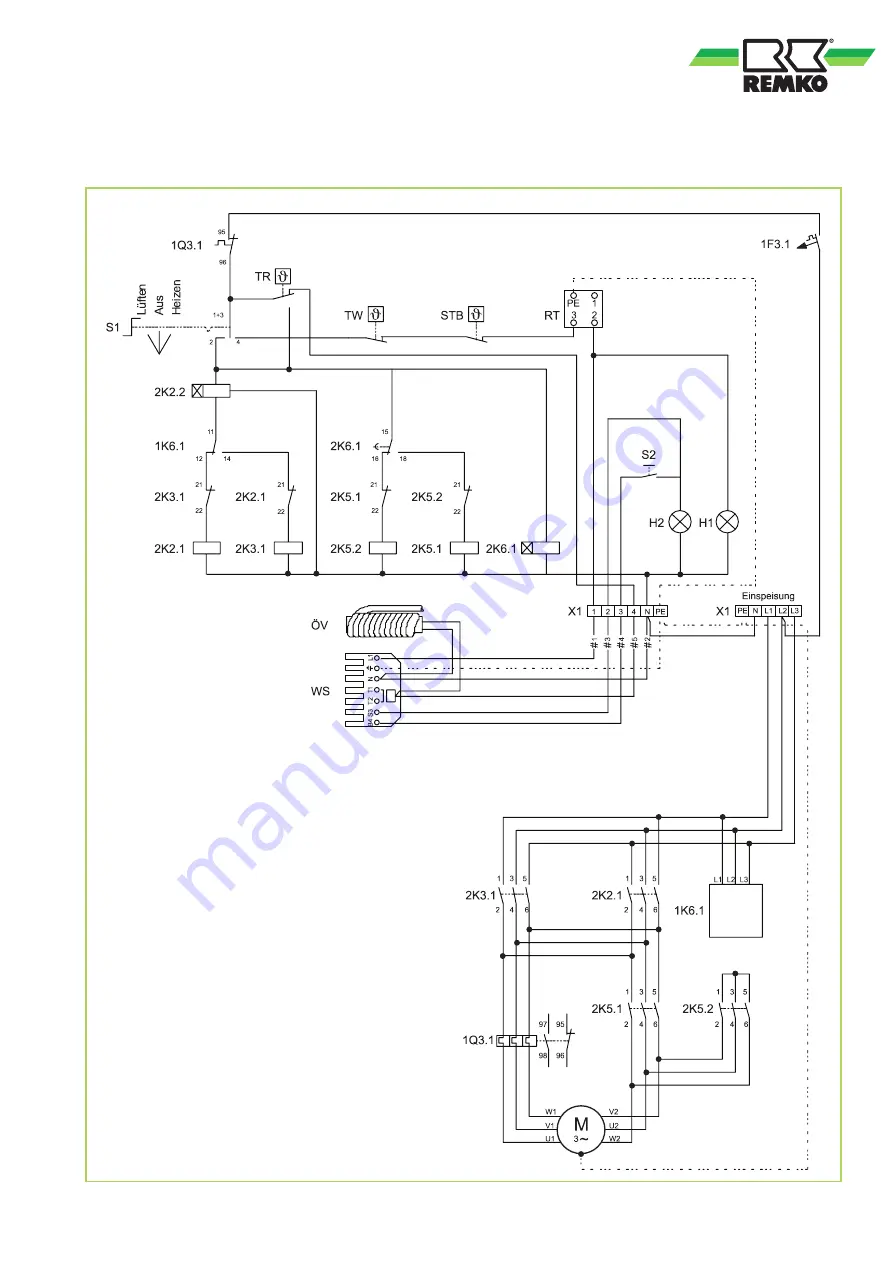
Electrical wiring diagram HTL 170
Load circuit
Control circuit
Legend:
S1 = Operating switch
S2 = Reset button (burner)
H1 = Operating lamp (green)
H2 = External burner fault lamp (red)
TR = Temperature controller
TW = Temperature monitoring device
STB = Safety temperature limiter
X1 = Terminal block
M = Fan motor
WS = Burner connector, 7-pole
RT = Thermostat receptacle
ÖV = Multiflex oil pre-heating
1F3.1 = Controller fuse
2K2.1 = Mains fuse
2K2.2 = Time relay
2K3.1 = Mains fuse
2K5.1 = Delta contactor
2K5.2 = Star contactor
1K6.1 = Phase sequence relay
2K6.1 = Star-delta relay
1Q3.1 = Motor overload protection switch
We reserve the right to modify the dimensions and design as part of the ongoing technical development process.


