8
Commissioning
Someone who has been sufficiently trained in the corre-
sponding handling of the unit must be assigned with its
operation and monitoring.
Important notice before the startup of a cold unit
The preheating of the nozzle stock delays the start of
the unit dependent on temperature.
Connecting the unit to the power supply
1. Switch the operating switch to the "0" position (off).
2. Connect the mains plug of the unit only to a properly
installed and sufficiently secured mains socket.
3. Open all shut-off fittings in the oil supply.
When operating the unit for the first time, air in the oil
supply can cause the burner to shut down due to a
malfunction.
Ventilation
In this switch position, only the supply air fan runs and
the unit can be used for air circulation.
1. Turn the operating switch to the "
II
" position
(ventilation).
2. Please note: in this mode, regulation of the
thermostat and heating mode are not possible.
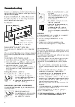
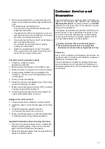
1. Connect the jumper plug (2) in-
cluded in delivery with the thermo-
stat socket (1) on the unit.
2. Switch the operating switch to the
"I" position (heating).
Heating without room thermostat
The equipment works in continuous operation.
1
2
1. Disconnect jumper plug 2.
2. Connect the plug (3) of the room ther-
mostat (4) together with the thermo-
stat socket (1) of the device.
Fully automatic heating with room thermostat
The unit operates fully automatically depending on the
room temperature.
1
3
4
Hot air distribution
The units are equipped with a high-performance axial
fan. This fan has been designed to transport the hot air
directly and effectively.
The distribution of the air should preferably take place
using the on-site outlet nozzle.
If necessary, pipes or special hot-air tubes or foil hoses
for air distribution in the possible area of fan output
(observe the channel resistance/equipment compres-
sion).
◊
Use only hot air tubes (accessories) approved by
Remko. In the process, pay attention to the air direc-
tion!
◊
To prevent heat from building up, the pipes and
tubes may not have sharp kinks and bends.
◊
Counterpressure may not be allowed to build up
when using tubes to heat enclosed spaces.
◊
If suction temperatures increase or if there is resis-
tance at the air output opening, the forced-air burner
can be switched off at short notice by the tempera-
ture monitor (TW) during heating.
When the temperature falls, the burner restarts auto-
matically.
◊
If the intervals are too short, the length of the hot air
pipes and tubes should be checked.
Avoid starting the burner in frequent cycles (run
times under five minutes).
If the temperature becomes too high, the heating
mode is interrupted permanently by the STB!
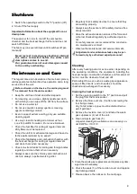
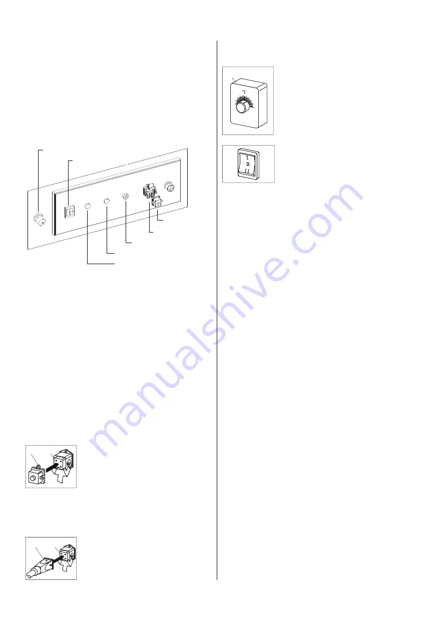
Operating switch
Control panel
Jumper plug
Thermostat socket
„Burner“ reset button
„Burner Fault“ red control lamp
„Operation“ green control
Safety temperature limiter
Note about the "Operation" control lamp
The control lamp indicates that the unit is in "Heating"
mode.
When the unit is in "Ventilation
"
mode, nothing is displayed
if the room thermostat is switched off or if the STB was ac-
tivated.
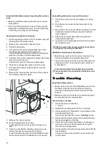
3. Place the room thermostat in a suit-
able spot.
The thermostat sensor may not be
located within the flow of hot air and
may not be directly attached to a
cold foundation.
4. Adjust the desired temperature on
the room thermostat.
5. Switch the operating switch to the
"I" position (heating).
If heat is needed, the forced-air
burner switches on automatically
and the unit functions fully automati-
cally.
Содержание CLK 20
Страница 2: ......


