16
Commissioning of the
Forced-Air Oil Burner
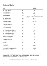
Required nozzle sizes
Selecting the required oil nozzle depends on the pump
pressure and the unit capacity. You may only use an oil
nozzle that is suitable for the shape of the respective
burner chamber with corresponding spray angle, cone
properties, and throughput. You can find the necessary
nozzle size in the technical data.
A
A
1
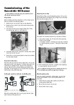
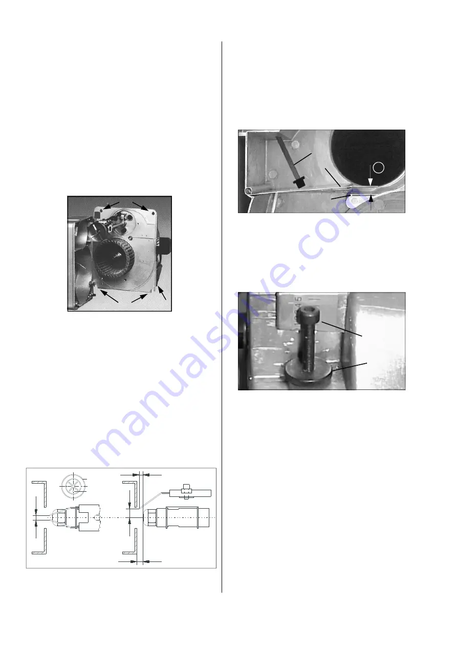
Mount the baffle plate (D) in such a way that the hole
(E) is flush with the photo cell.
Preparation
Before starting with the adjustment of the forced-air oil
burner, perform the following tasks:
1. Remove the cover of the burner compartment.
2. Remove the fuel line from the burner and pull the
burner plug.
3. Unscrew the four quick-release fasteners of the
mounting base plate (1) at Position A.
The forced-air oil burner may be commissioned
only by expert personnel!
Setting the ignition electrode and baffle plate
All dimensions are approx. values
in mm.
D
E
4
5
4
3
Mounting base plate
After the ignition electrode, baffle plate, and air inlet
nozzle are adjusted, the mounting base plate is re-
mounted.
1. Attach the mounting base plate using the four
quick-release fasteners.
2. Mount the fuel line to the burner.
3. Reinsert the burner plug.
Adjusting the air flap
Adjust the air flap using the adjusting screw (7) in such a
way that Distance A between the air flap (8) and the stop
(9) amounts to approx. 6 mm.
To adjust the necessary distance, proceed as follows:
1. Loosen the knurled nut (10) and turn the adjusting
screw (7) accordingly.
Clockwise rotation:
Distance A becomes smaller
Counterclockwise rotation:
Distance A becomes
larger
A
7
8
9
10
7
2. After adjusting the distance, retighten the adjusting
screw using the knurled nut (10).
The optimum setting must be adapted to the lo-
cal conditions and the respective chimney.
4. Carefully remove the complete mounting base plate
from the front of the unit.
5. Place the mounting base plate somewhere suitable
for the further tasks.
D
Содержание CLK 20
Страница 2: ......


