13
TW
RT
TR
STB
S1
WS
1A
2A
3A
4B
5B
6B
H2
H1
KL
1
2
3
4
5
6
7
8
9
L
1
N
T
1
T
2
S
3
B
4
I
0
II
C
10
2
1
3
S2
M
N
braun
orange
schwarz
1
1
1
2
2
2
4
4
#
2
#
4
#
3
N
PE
L1
N
HW 04.03
blau
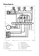
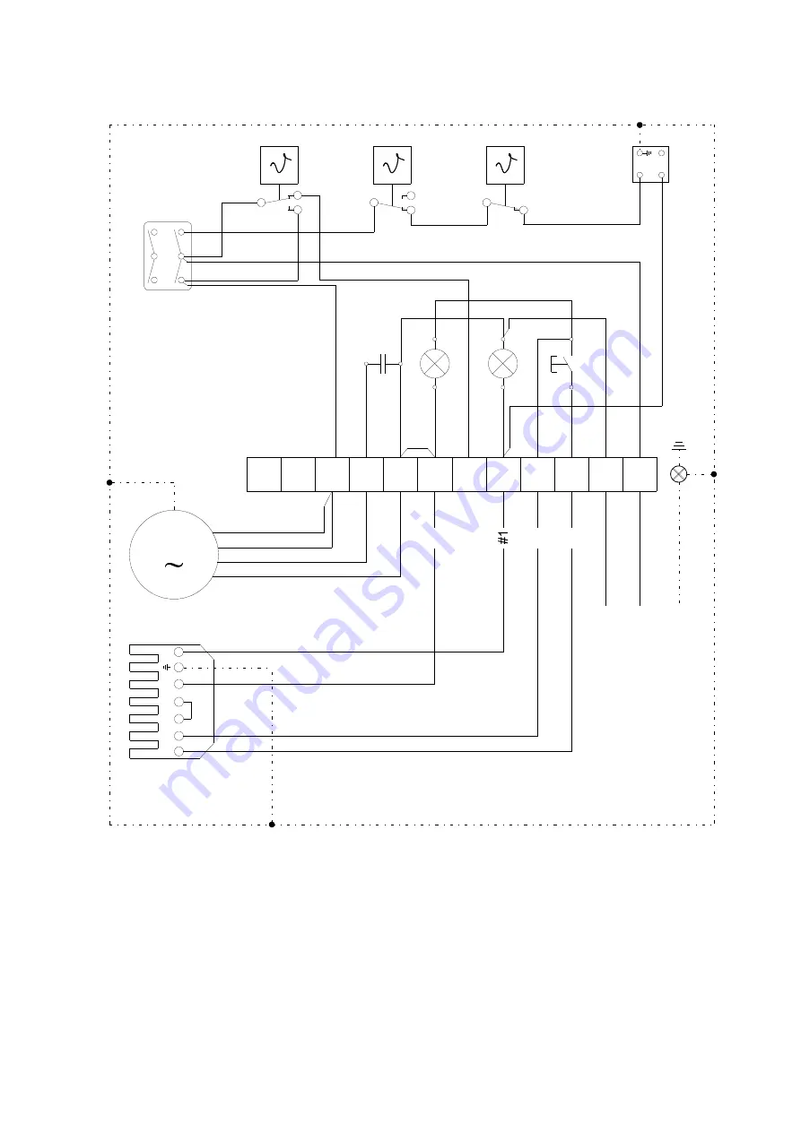
Wiring Diagram
C = Capacitor
S1
= Operating switch
H1 = Control lamp (green)
S2
= Reset button (burner)
H2 = External control lamp (red)
STB = Safety temperature limiter
KL = Terminal strip
TR = Temperature control thermostat
M = Fan motor
TW = Temperature monitor
RT = Thermostat socket
WS = Burner plug, 7-pole
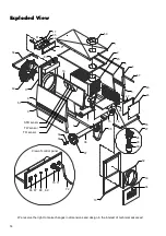
We reserve the right to make changes in dimensions and design in the interest of technical advances.
Brown
Orange
Black
Blue
Содержание CLK 20
Страница 2: ......


