background image

Controls

Function

6

Correktion of wire speed


Fine adjustment for wire speed in addition to the machine calculated 

speed by adjustments of you did with the rotary cam switches 11 and 

12. The correction value stays active even if you change steps.


Negative correction = reduces wire speed     => arc gets longer


Positive correction   = increases wire speed  => arc gets shorter


If arc energie gets too low and welding result isn‘t convinient you 

need to change output voltage by the rotary switches.
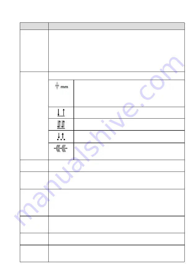
7

Mode switch

Auxiliary function to find the right adjustment for a 

certein material thickness. 7-Segment indicator 2.


For control reason value of calculated material thickness 

is show shortly when activating the torch button.


If arc is astablished indicator show welding current.

2-Step mode

4-Step mode

Spot welding - time adjust with potentiometer 8

Pulse welding - Interval welding


Pulse time can be adjusted with regulator 8, 


the pause time is half the pulse time.

8

Time setting


for functions spot and pulse welding [0.1 ... 5.0 sec]

9

Material selection switch

Selection of material like aluminium, copper (CuSi3), steel and stain-

less steel (CrNi) and wire thickness like 0.8, 1.0, 1.2 mm

10

SDI adjustment


Stepless adjustable DC choke to allow hard or soft welding arc.


If potentiometer is in the left stop position Automatic SDI is switched 

on. Now application controller is calculating adjustment according to 

position of rotary switches.

11

Rotary cam switch  -  coarse adjustment


Not available in all products. Big increase of output voltage and 

welding current.

12

Rotary cam switch  -  fine adjustment


Stepwise increase of voltage and current.

13

FOCUS switch


Arc will be focussed. Available only at products 304, 404 und 504 and 

only for steel and stainless steel welding.


Содержание SYNERGIC.PRO 251

Страница 1: ...NIK REHM SCHWEISSTECHNIK SHORT MANUAL SYNERGIC PRO 251 311 351 352 402 304 404 504 This short manual does not substitute the original operator manual Please read this document carefully before your st...

Страница 2: ...l the use of safety devices is not permitted This invalidates the guarantee and the reliability claim If external agents are used e g solvents for cleaning the operator of the system must guarantee th...

Страница 3: ...Intended Use The MIG MAG welding systems are only to be used for MIG MAG or manual electrode welding for hand guided and machine guided operation see original operating instructions for welding metal...

Страница 4: ...2 Design and Connections Compact welding machine 251 311 351 Compact machine 352 402 Compact machine 304 404 504 Welding machine with separate wire feeder unit 304S 404S 504S...

Страница 5: ...chine and material Otherwise current flow is uncontrolled and is searching a path to potential earth Damages are possible 4 Cooling water connections blue Cold water red hot water 5 Air entrance area...

Страница 6: ...onnected to the torch Arc ingnition will be activated if wire touches material 4 Control LED Temperature gelb If temperature gets too high the machine switches off the power to protect internal power...

Страница 7: ...ode 4 Step mode Spot welding time adjust with potentiometer 8 Pulse welding Interval welding Pulse time can be adjusted with regulator 8 the pause time is half the pulse time 8 Time setting for functi...

Страница 8: ...low time The default value is 0 2 sec after releasing torch trigger button Thread in automatic With press and hold torch button in 2 step mode the automatic phase to thread the wire startes if system...

Страница 9: ...ettings Specialists only Function Description details Specialists can use the R59 R60 and R61 trim resistors to change the settings for the following functions Burn wire free time Creep speed Gas post...

Страница 10: ...r the wire are driven the rolls on top of the wire are free running pinch rollers 1 Adjust contact pressure to the wire Use the red screws Unlock and tilt pinch roller to the side of the door for thre...

Страница 11: ...ferent wire diameter e g 0 8 1 0 mm Quick release system In mounted position a label with active diameter in different colors is visible To use the other groove please turn the roller t Standard from...

Страница 12: ...ear the noise of the pump Daily Check cooling air channel The air must circulate freely for cooling Do not place obstacles in the air flow Daily Blow out filters Clean air paths and filters with compr...

Страница 13: ...ight Grid On is off A line is missing Check fuse F1 and F2 on power supply and filter board Control light temperature too high is on Thermal protection is actice Let it cool down Control light Operati...

Страница 14: ...122201 Synergic Pro 351 1031127 Synergic Pro 304 W 1122202 Synergic Pro 352 W 1031130 Synergic Pro 304 WS 1122203 Synergic Pro 402 W 1031131 Synergic Pro 404 1122210 Synergic Pro 404 S 1122211 Synergi...

Страница 15: ...e above products comply with the requirements of this directive and comply with the safety requirements for arc welding units in accordance with the following pro duct standards EN 60 974 1 2018 12 Ar...

Страница 16: ...nt Welding filler metals Welding extraction systems Rotating tables Cobot systems Consulting Repair service Service Development construction and production all under one roof in our factory in Uhingen...

Отзывы: