Commissioning
Reflexomat XS — 02.16.2022 - Rev. A
English — 21
6.5
Power Supply
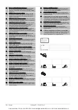
DANGER
Risk of serious injury or death due to electric shock.
If live parts are touched, there is risk of life-threatening injuries.
•
Ensure that all phases of the mains power supply to the product are
disconnected prior to installation.
•
Ensure that the system is secured and cannot be reactivated by other
persons.
•
Ensure that installation work for the electric connection of the device is
carried out by an electrician, and in compliance with electrical
engineering regulations.
All electric connections between control unit and expansion vessel are pre-
installed.
1.
Connect the mains plug to the 230 V power supply.
2.
Activate the system.
The electrical connection is completed.
6.5.1
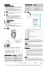
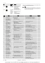
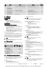
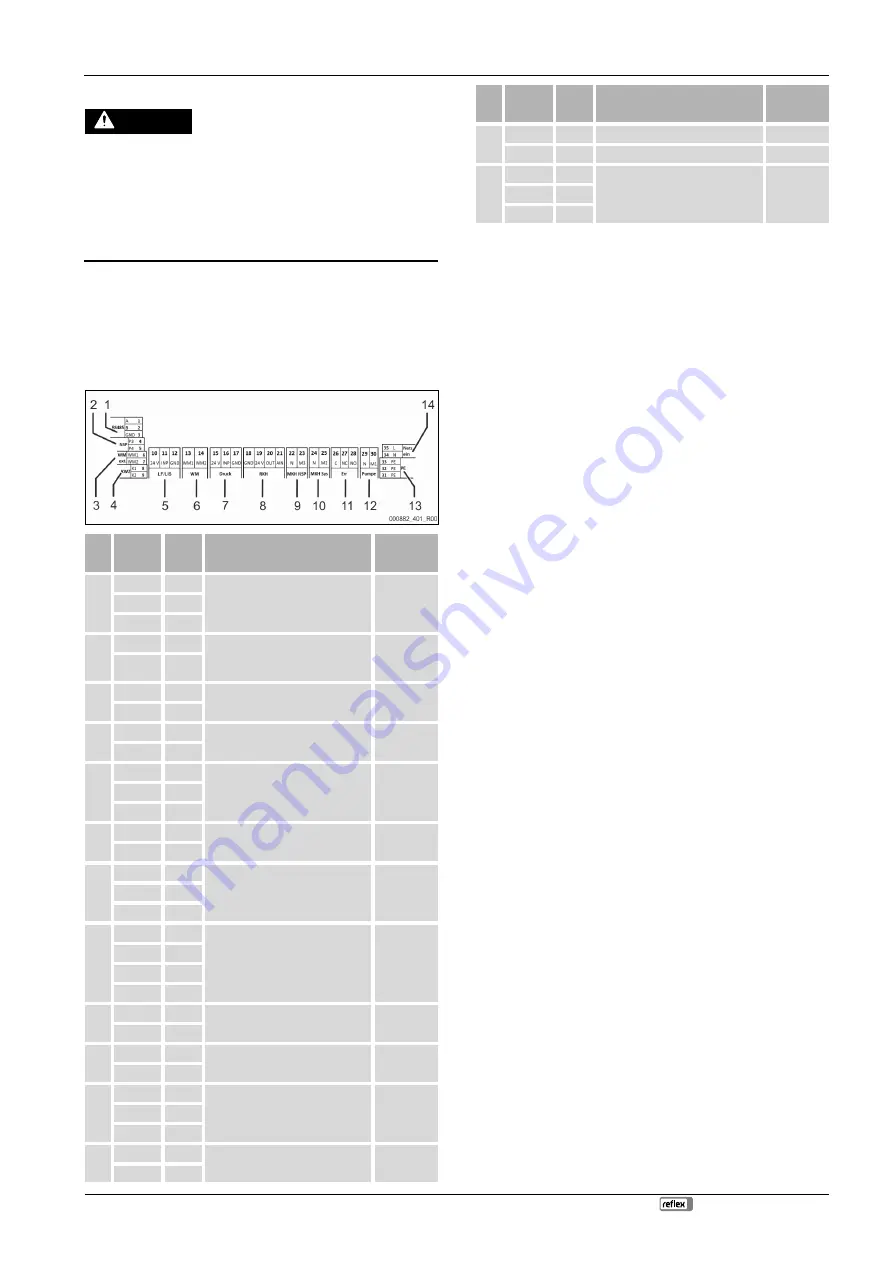
Terminal diagram
Item
no.
Terminal
number
Signal
Function
Wiring
1
1
GND
RS485 interface for Modbus RTU or
proprietary Reflex protocol
On-site,
optional
2
A
3
B
2
4
P3
External make-up request
•
With the Levelcontrol setting.
Input 230 V signal via L+ N
On-site,
optional
5
P4
3
6
WM1
---
---
7
WM2
4
8
K1
Contact water meter
•
Digital input
On-site,
optional
9
K2
5
10
24 V
Filling level measurement
•
Analogue input 4-20 mA
Factory
11
INP
12
GND
6
13
WM1
---
---
14
WM2
7
15
24 V
Pressure sensor
•
Analogue input 4-20 mA
Factory
16
INP
17
GND
8
18
GND
---
---
19
24 V
20
OUT
21
AIN
9
22
N
Make-up request 230 V
On-site,
optional
23
M3
10
24
N
Solenoid valve on the air side
Factory
25
M2
11
26
C
Potential-free group alarm contact
(max. 230 V / 8 A)
On-site,
optional
27
NC
28
NO
12
29
N
Compressor/relief valve
Factory
30
M1
Item
no.
Terminal
number
Signal
Function
Wiring
13
31
PE
Earthing
Factory
32
PE
Earthing
Factory
14
33
PE
230 V voltage supply via cable with
power plug.
Factory
34
N
35
L
6.5.2
RS-485 interface
This interface is used to retrieve all controller data and to enable communication
with control centres or other devices.
The following data can be requested:
•
Pressure and filling level.
•
Compressor operating states.
•
Operating states of make-up via solenoid valve.
•
Aggregate volume of the FQIRA + contact water meter.
•
All messages,
•
All entries in the error memory.
6.5.2.1
Connecting the RS-485 interface
•
Use a shielded cable to connect the interface to terminals 1 – 6 of the
circuit board in the control cabinet.
–
For connecting the interface,
•
When using the device with a control centre not supporting an RS-485
interface (RS-232, for example), you must use a corresponding (on-site)
adapter.
Note!
For connecting the interface use, for example, a cable with these
properties.
•
LIYCY (TP), 4 × 2 × 0.8, maximum overall bus cable length 1000 m.
6.6
Installation and commissioning certificate
Note!
The installation and commissioning certificate can be found at the end
of the operating manual.
7
Commissioning
Note!
Commissioning and maintenance work must be carried out and
confirmed by specialist personnel or the Reflex Customer Service.
Note!
The app guides you through commissioning
7.1
Requirements for initial commissioning
The Reflexomat will be ready for initial commissioning when the tasks described
in the "Installation" chapter have been completed.
•
The Reflexomat has been located.
•
The weight measuring cell is connected.
•
The water-side connection of the vessel to the system circuit has been
established.
•
The vessel is not filled with water.
•
The connection pipes of the Reflexomat have been purged and cleaned of
welding residue and dirt before commissioning.
•
The draining valves of the vessel are open.
•
The entire system has been filled with water and all gases have been
vented in order to ensure circulation throughout the entire system.
•
The electrical connection has been created according to applicable
national and local regulations.
7.2
Reflexomat switching points
The "P
0
" minimum operating pressure is determined by the location of the
pressure maintenance system. The controller calculates the switching points for
the "PV" solenoid valve and the "CO" compressor from the "P
0
" minimum
operating pressure.
Cooke Industries - Phone: +64 9 579 2185 Email: [email protected] Web: www.cookeindustries.co.nz


