background image


Redpine Signals, Inc. Proprietary and confidential 

Page 31 

R

R

S

S

9

9

1

1

1

1

0

0

-

-

N

N

-

-

1

1

1

1

-

-

2

2

2

2

/

/

2

2

4

4

/

/

2

2

6

6

/

/

2

2

8

8


S

S

e

e

l

l

f

f

-

-

C

C

o

o

n

n

t

t

a

a

i

i

n

n

e

e

d

d


W

W

L

L

A

A

N

N


M

M

o

o

d

d

u

u

l

l

e

e

s

s


w

w

i

i

t

t

h

h


N

N

e

e

t

t

w

w

o

o

r

r

k

k

i

i

n

n

g

g


S

S

t

t

a

a

c

c

k

k


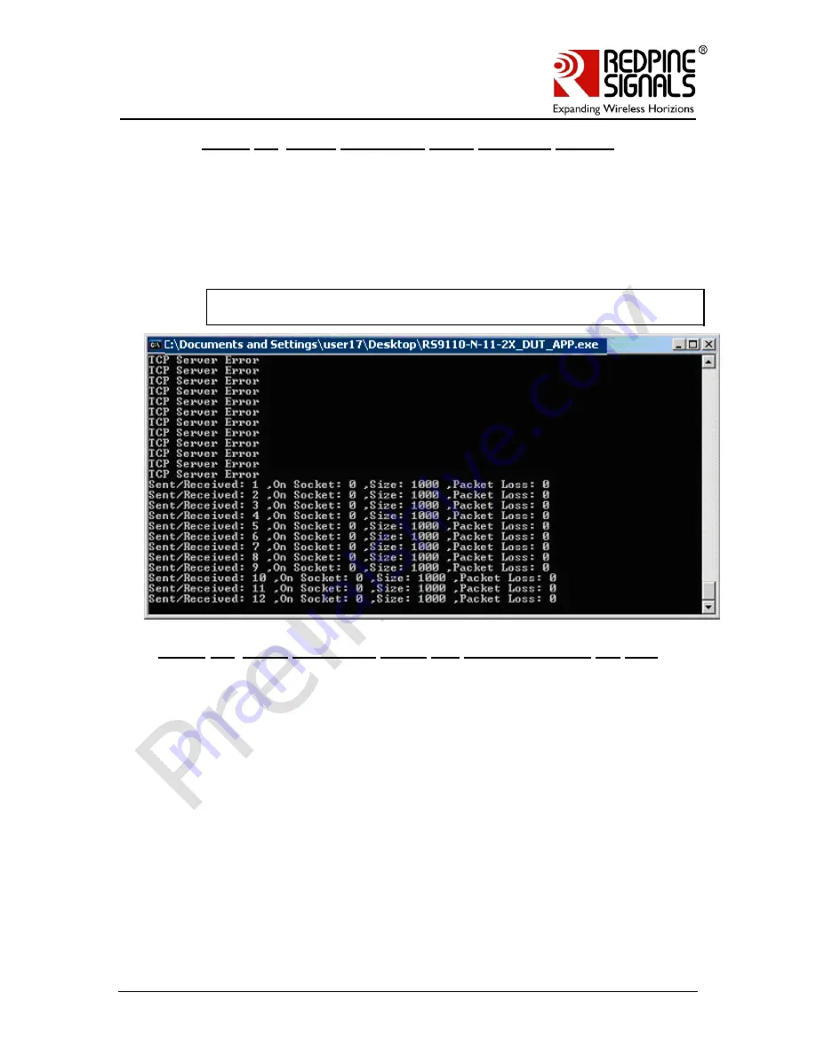
Figure 26: 


Server Application Starts Receiving Packets 


2.5.3.3:


Send And Receive Data (TCP Server) 

If a TCP server (LTCP) socket is created, the connection is established only when 

the TCP peer connects with the server. The DUT application queries for the 
connection status on a particular TCP server socket till the connection is 

established. Once the connection is established, the transmission and reception 
of the data happens as shown in the figure below. 

NOTE: In case of TCP Server Socket (LTCP) Destination IP address and 
Destination port number should be zero. 


Figure 27: 


Query Connection status and transmit/receive the data 


2.5.3.4:


List Sockets  

The List Sockets option lists the active sockets at a particular instance. The 

socket descriptor and the socket type are displayed as below. 
 

Содержание RS9110-N-11-22

Страница 1: ... V Ve er rs si io on n 1 1 1 13 3 April 10 Redpine Signals Inc 2107 N First Street 680 San Jose CA 95131 Tel 408 748 3385 Fax 408 705 2019 Email info redpinesignals com Website www redpinesignals com Redpine Signals Inc 2107 N First Street 680 San Jose CA 95131 Tel 408 748 3385 Fax 408 705 2019 Email info redpinesignals com Website www redpinesignals com ...

Страница 2: ...for Application Processors Industrial M2M communications Point of Sale Terminals Metering Parking Meters Utility Meters Power Meters etc Security Cameras and Surveillance Equipment Logistics and Freight Management Warehousing Digital Picture Frames Several medical applications including Patient Monitoring Remote Diagnostics Device Features Compliant to 802 11b g 802 11a and single stream draft 802...

Страница 3: ...am RS9110 N 11 22 RS9110 WLAN Subsystem RS9110 RF Transceiver Flash XO Serial I f 3 3V Supply RF FE SPI Host I f Reset LED Reset BT Coexistence I f Test Port Host Processor UART Port Applications TCP UDP WLAN Stack SPI UART Selection GPIO Flash RS9110 N 11 24 System Block Diagram RS9110 N 11 24 RF Transceiver PA Balun Flash T R Switch UART SPI 3 3V Peripheral I O GPIO Reference Frequency BT Coexis...

Страница 4: ...ce i f UART SPI Select RESET XO LED Flash Reset UART SPI Host Processor Applications RS9110 N 11 28 System Block Diagram RS9110 N 11 28 RF Transceiver PA Balun Flash T R Switch 3 3V Peripheral I O GPIO 5G Reference Frequency RS9110 TCP UDP WLAN Stack Balun Diplexer 2 4G Diplexer 5 GHz 2 4 GHz Diversity Antennas Reset BT Coexistence i f UART SPI Select UART SPI Hos t Process or Applications Documen...

Страница 5: ... W WL LA AN N M Mo od du ul le es s w wi it th h N Ne et tw wo or rk ki in ng g S St ta ac ck k RS9110 N 11 22 RS9110 N 11 24 RS9110 N 11 26 RS9110 N 11 28 With XO Antenna Without XO Antenna Single Band 2 4 GHz RS9110 N 11 2X Option for u FL connector for External Antenna Hardware Differentiation With XO Antenna Without XO Antenna Dual Band 2 4 and 5 GHz ...

Страница 6: ...2 2 5 Connect to a Hidden Access Point 18 2 2 6 Creating a IBSS Network 18 2 3 IP Address Configuration 19 2 3 1 Manual Configuration 19 2 3 2 DHCP Configuration 20 2 4 Disconnect from Access Point 21 2 5 TCP UDP IP Evaluation 22 2 5 1 DUT Application 22 2 5 2 Peer Application 23 2 5 3 Test setup and Evaluation 23 2 5 3 1 Create Sockets 26 2 5 3 2 Send And Receive Data UDP TCP Client LUDP 29 2 5 3...

Страница 7: ...re 17 Startup window of UDP Client Application 25 Figure 18 COM Port opened successfully by the Client application 25 Figure 19 Enter Socket type 26 Figure 20 Socket type TCP 27 Figure 21 Socket type UDP 27 Figure 22 Socket type LTCP 28 Figure 23 Socket Type LUDP 29 Figure 24 Parameters and Result for Send and Receive Data on UDP Socket 29 Figure 25 Parameters and Result for Send and Receive Data ...

Страница 8: ...verview The following diagram depicts the software architecture of the RS9110 N 11 2X module SLIP UART HOST PROCESSOR HOST RS9110 N 11 2X Host Abstraction Layer Station Managment Entity 802 11 b g n MAC TCP IP Wireless Control Block SPI WPA WPA 2 UART Driver SPI Driver UART SPI Application Figure 1 RS9110 N 11 2X Software Architecture Block Diagram Redpine Signals Inc Proprietary and confidential ...

Страница 9: ...er in setting up the Evaluation Board EVB of the RS9110 N 11 2X module to be used as a Wireless Device Server and interact with Applications on the Host using the UART interface The following topics are discussed Procedure to use the Wi Fi Config Utility GUI which configures the RS9110 N 11 2X module Procedure to evaluate the TCP IP UDP IP protocols using RS9110 N 11 2X module Procedure to perform...

Страница 10: ...S9110 N 11 2X EVB 1 Connect the Male end of the supplied serial cable to the RS9110 N 11 2X EVB s serial port 2 Connect the Female end of the DB9 serial cable to a PC s serial COM port 3 Connect the USB power cable to the RS9110 N 11 2X EVB and to a power outlet and switch on the power to the EVB by toggling the Power Switch refer to the figures below DB9 Connector RS9110 N 11 22 Module LED USB Po...

Страница 11: ...ity NOTE Please make sure that the EVB is powered on the LED is glowing and the serial cable is connected before proceeding with the steps in the following sections 2 2 Configuring the RS9110 N 11 2X Module The Wi Fi Config Utility is a GUI based application used to configure the RS9110 N 11 2X module To execute this utility double click on the executable RS9110 N 11 2X exe found in the CD in the ...

Страница 12: ... beside the Baud Rate label NOTE PCs and Laptops with Windows XP usually support a maximum baud rate of 115200 bps If a higher baud rate is selected e g in a Hyperterminal the observation has been that the baud rate that is actually used is 115200 bps This will be true for the Wi Fi Config Utility as well This is a limitation of the PC rather than of the RS9110 N 11 2X EVB 3 In case the user wants...

Страница 13: ...ayer inbuilt in the RS9110 N 11 2X module The procedure to perform the above mentioned actions are discussed in the following sections 2 2 1 Initialize the COM port of the PC The following steps are to be followed to initialize the COM port of the PC to which the RS9110 N 11 2X module is connected 1 In order to initialize the COM port the correct COM port name has to be entered in the GUI 2 To kno...

Страница 14: ... In the window that opens click on the Hardware tab followed by the Device Manager button 4 In the new window that opens double click on Ports COM LPT 5 The COM port name is the data in the brackets as shown in the screenshot below COM Port Name Figure 6 COM Port Name 6 IBSS In the Wi Fi Config Utility enter the COM port name and click on Open 7 The display on the bottom left corner shows that the...

Страница 15: ... the connection between the PC and the EVB not being proper It s recommended that the serial cable be used directly without adapters like a USB to Serial adapter 2 2 2 Scan To scan for the available Access Points and IBSS Stations in all channels click the SCAN button The list of scanned Access Points and IBSS Stations is displayed on the GUI as shown below The SSID corresponds to the SSID of the ...

Страница 16: ...The following actions are to be performed to connect to an Access Point 1 Select a specific SSID in the list by clicking on it 2 Enter the Pre Shared Key if the Access Point is configured to be in either WEP WPA or WPA2 mode5 3 Select the transmission rate and power The modes of power are LOW 7 dBm MEDIUM 10dBm and HIGH 15dBm 4 Click the CONNECT button to connect to the selected Access Point 5 The...

Страница 17: ...onnected to the WLAN network 2 2 4 Connect to an IBSS Network To connect to an IBSS Network the following steps are to be followed 1 Select a specific IBSS SSID in the list by clicking on it 2 Select the transmission rate and power The modes of power are LOW 7 dBm MEDIUM 10dBm and HIGH 15dBm 3 Select the Network type as IBSS 4 Click the CONNECT button to connect to the selected IBSS Network 5 The ...

Страница 18: ...nown the following steps are to be followed 1 Click the SSID button 2 Enter the SSID in the adjacent text field 3 If security is enabled enter the Pre Shared Key 4 Click the CONNECT button to connect to the Access Point 2 2 6 Creating a IBSS Network To create an IBSS Network the following steps are to be followed 1 Enter the network name SSID in the IBSS Creation section of the GUI 2 Select the Ch...

Страница 19: ... the module the same steps are to be followed as before 2 3 IP Address Configuration The RS9110 N 11 2X has an inbuilt TCP UDP IP stack and thus provides an option for the Host to transmit only application data which is transmitted over WLAN after TCP UDP packetization The TCP IP stack has to be configured with the IP Address Subnet Mask and Gateway Address The Configuration can be done in two way...

Страница 20: ...format 4 Enter the Gateway Address in the dotted decimal format 5 Click OK to complete the configuration Figure 12 IP Address Configured 2 3 2 DHCP Configuration The user has to perform the steps below to obtain the IP address 1 Select the DHCP Radio button from IP Configuration section of the configuration utility 2 Select the mode of reception of the data from the TCP IP stack to the application...

Страница 21: ... off and then powered on it has to be configured with the values again In future firmware releases this will not be required NOTE The IP address Subnet Mask and Default Gateway have to be configured through the GUI in case of manual mode by clicking the OK button prior to executing the applications used to validate the TCP IP stack 2 4 Disconnect from Access Point The DISCONNECT button can be used...

Страница 22: ...upplied 2 5 1 DUT Application The DUT Application RS9110 N 11 2X_DUT_App exe is to be executed in the PC to which the RS9110 N 11 2X EVB is connected using the RS232 cable It communicates with the TCP IP stack in the RS9110 N 11 2X module over the UART interface through AT commands Please refer to the programmer s reference manual for the description of the AT commands The application RS9110 N 11 ...

Страница 23: ...erver PC Windows XP RS232 RS9110 N 11 22 EVB Access Point TCP UDP Server Client PC Windows XP Linux 1 2 Figure 15 Test setup for TCP UDP IP Evaluation6 To run the test please follow the steps below 1 Make sure that the Access Point and the Server Client PC s are connected properly and are on the same network If they are on different networks ensure proper routing between them 2 Make sure that the ...

Страница 24: ...X_TCP_App_Client exe yyy yyy yyy yyy xxxx On Linux RS9110 N 11 2X_TCP_App_Client yyy yyy yyy yyy xxxx Where xxxx is the port number and yyy yyy yyy yyy is the IP address in the dotted decimal format NOTE 2 The TCP server and the UDP server take only the port number as the input whereas the TCP client takes the IP address and the port number as inputs These parameters correspond to the IP address a...

Страница 25: ...le es s w wi it th h N Ne et tw wo or rk ki in ng g S St ta ac ck k Figure 17 Startup window of UDP Client Application 7 Enter the name of the COM Port To know the COM Port to which the RS9110 N 11 2X EVB is connected follow the steps given in Section 2 2 1 The following screen appears asking the user to enter a choice Figure 18 COM Port opened successfully by the Client application ...

Страница 26: ...e following sections explain the description of each choice with the screen shots 2 5 3 1 Create Sockets 1 Enter 1 Create Sockets as the choice 2 The application asks to enter the type of socket as shown below Figure 19 Enter Socket type 3 If the choice entered is 0 a TCP client socket is created The application asks for the local port number of the socket destination IP address and the destinatio...

Страница 27: ...t tw wo or rk ki in ng g S St ta ac ck k Figure 20 Socket type TCP 4 If the choice entered is 1 a UDP socket is created The application asks for the local port number of the socket destination IP address and the destination port number of the application on the peer Figure 21 Socket type UDP 5 If the choice entered is 2 an LTCP Listening TCP socket is created This will create a TCP server socket w...

Страница 28: ...ing on a given port number for the connection to be established by a TCP client The application asks for the local port number on which the socket should listen Figure 22 Socket type LTCP 6 If the choice entered is 3 an LUDP Listening UDP socket is created This will create a listening UDP server socket which will be listening on a given port number for the data from any peer The application asks f...

Страница 29: ...destination IP address the destination port and the number of packets to be sent and received on each socket The number of sockets specifies the total number of sockets on which the data has to be sent and received The socket numbers signify the sockets on which the data has to be sent and received The sockets have to be created for the data transmission and reception to happen If a wrong socket n...

Страница 30: ... on TCP Socket The application starts transmitting and receiving the data packets through the RS9110 N 11 2X module over Wi Fi The application displays the statistics as shown in the figure above The application compares the received data with the sent data Any failure in the comparison results in a packet loss and is displayed accordingly The application sends and receives the number of packets s...

Страница 31: ... only when the TCP peer connects with the server The DUT application queries for the connection status on a particular TCP server socket till the connection is established Once the connection is established the transmission and reception of the data happens as shown in the figure below NOTE In case of TCP Server Socket LTCP Destination IP address and Destination port number should be zero Figure 2...

Страница 32: ... on nt ta ai in ne ed d W WL LA AN N M Mo od du ul le es s w wi it th h N Ne et tw wo or rk ki in ng g S St ta ac ck k Figure 28 List Sockets 2 5 3 5 Close Sockets The Close Sockets option closes an active socket The socket descriptor of the socket to be closed is the parameter for this option as shown below Figure 29 Close Sockets ...

Страница 33: ...time configured with the Sleep Timer option in the Power Save submenu The unit for the sleep timer is milliseconds The default value of the Sleep Timer is 100 ms The maximum value that can be configured is 10000 ms Figure 30 Sleep Timer Configuration 2 5 3 6 2 Power Mode 1 unconnected state To trigger the power modes enter choice 5 in the main menu The following screen shot shows the menu on selec...

Страница 34: ...configure the sleep timer before configuring the module for Power Mode 1 Figure 31 Power Mode 1 Before WLAN Connection 2 5 3 6 3 Power Mode 2 unconnected state To trigger the power modes enter the choice 5 in the main menu The following screen shot shows the menu for the Power Mode 2 Mode 2 There is no negotiation with the host in this power mode Thus the module is in this mode till the user switc...

Страница 35: ...nfigured with an IP address using the Configuration GUI After selecting the Power Mode 1 in the console the user is prompted to Enter the number of ACKs to be issued for the Sleep The DUT application sends the configured number of ACK messages for the obtained SLEEP messages before sending receiving each data packet The module continuously issues the SLEEP message after every DTIM period to query ...

Страница 36: ... th h N Ne et tw wo or rk ki in ng g S St ta ac ck k Figure 33 Power Mode 1 After WLAN Connection 2 5 3 6 5 Power mode 2 connected state To test Power Mode 2 in connected state the module has to be connected to an Access Point and configured with an IP address using the Configuration GUI The following screen shot shows the selection of the Power Mode 2 Figure 34 Power Mode 2 After WLAN Connection ...

Страница 37: ...connection For this the user need to close the Test Applications and restart the GUI since the COM port can be used only by one application at any time When the GUI is opened it will try to perform the ABRD process again and fail Only after the failure the DISCONNECT button will be enabled Of course in an embedded environment the user can directly issue the disconnect command AT RSI_DISASSOC witho...

Страница 38: ...e terminal with the following settings Baud Rate 115200 Stop Bits 1 Parity No Flow Control No 5 Switch on the power to the EVB by toggling the Power Switch on the EVB 6 The module is configured for Auto Baud Rate Detection ABRD and hence the module waits for approximately 40 to 50 seconds for ABRD message exchange to be initiated by the Host as described in the Software PRM However in the case of ...

Страница 39: ...prompt from the user and hence the user has to enter y as soon as the prompt appears 8 The user has to now transfer the firmware files The files viz taim1 taim2 tadm1 and tadm2 present in the Firmware folder of the CD have to be transferred in the same order from the HyperTerminal The following is the procedure to send a file through the HyperTerminal 9 Click on Transfer on the toolbar of the Hype...

Страница 40: ...k k Figure 36 Transferring taim1 14 For each file being transferred wait for a display on the Hyperterminal which says Send nextfile Please note that after a file is transmitted there is some delay is writing the data to the non volatile memory This might take a few seconds and the user has to wait for the prompt on the Hyperterminal for the next file 15 Once all three files are transferred the fo...

Страница 41: ... 11 10 0 N N 1 11 1 2 22 2 2 24 4 2 26 6 2 28 8 S Se el lf f C Co on nt ta ai in ne ed d W WL LA AN N M Mo od du ul le es s w wi it th h N Ne et tw wo or rk ki in ng g S St ta ac ck k Figure 37 Firmware upgrade successful You are now ready to work with the new firmware ...

Страница 42: ...e user to configure it for different scenarios7 The figure below shows the various components DB9 Connector RS9110 N 11 22 Module LED USB Power Supply Power Switch Header J7 SPI DIP Switches Switch SW4 Switch SW5 Header J6 UART Push Button Reset Header J4 Debug Figure 38 Components on the EVB of RS9110 N 11 22 24 Modules 7 Some of the older revisions of the EVB may not contain all the components d...

Страница 43: ...eset or Push Button Reset 2 Select between SPI and UART modes 3 Debug DIP Switches 1 and 2 are used to configure the source of the Reset for the module Placing DIP Switch 1 towards the ON label and DIP Switch 2 towards the opposite side selects the Power On Reset Flipping the switches Switch 2 towards ON and Switch 1 in the opposite side selects the Push Button Reset DIP Switch 3 is used to select...

Страница 44: ...er bypasses the DB9 connector and the 3 3V 5V level shifter ICs and a simple ribbon cable can be used for this interface This header can be enabled disabled by flipping the switches SW4 and SW5 The pin configuration of this header is as follows Figure 41 Pin Configuration of Header J6 4 5 Switches SW4 and SW5 The Switches SW4 and SW5 are used to select between the DB9 connector and the Header J6 f...

Отзывы: