


OPERATION
To Operate the
Flowmeter
PRESET MODELS
To Stop In Emergency
To Adjust Tripping
Point
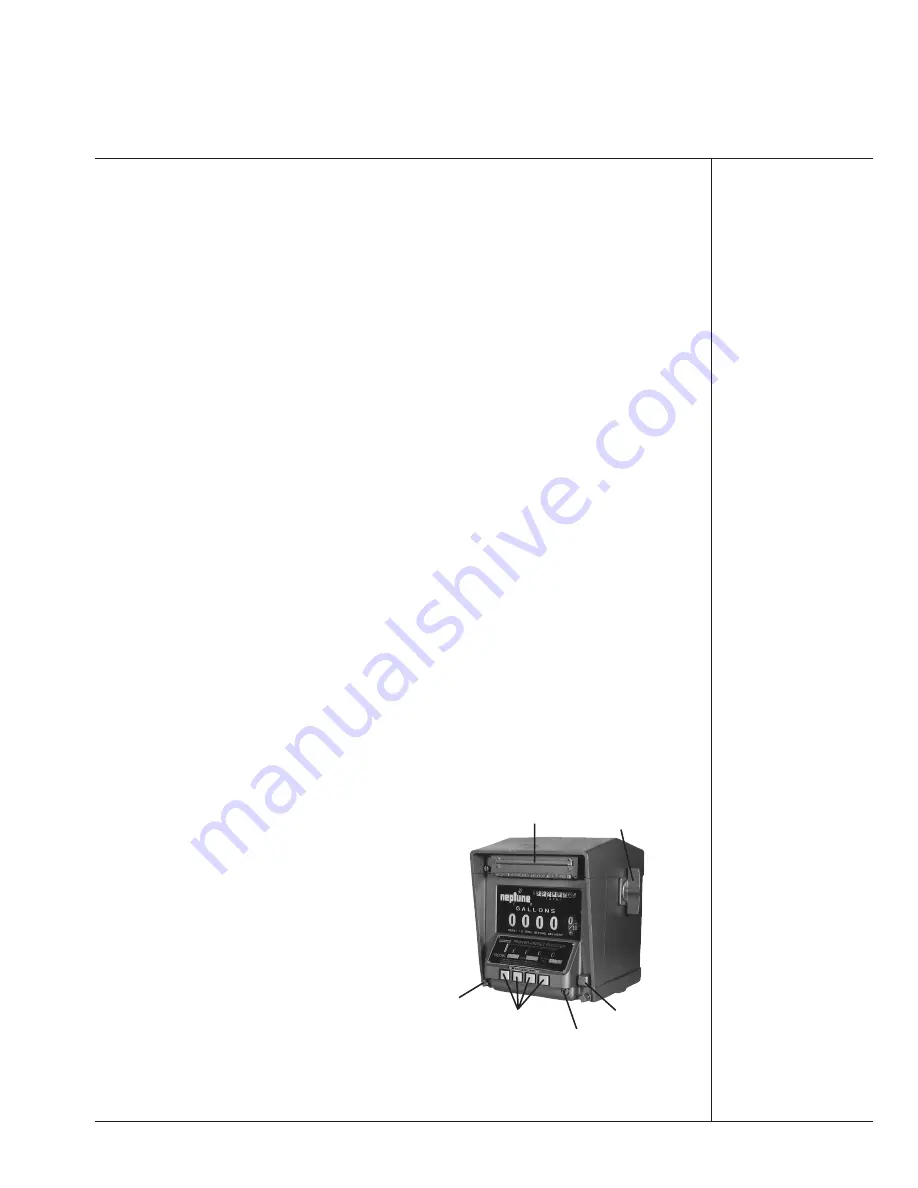
FIGURE 3
PRESET 800 SERIES
PRINTER REGISTER
Page 3
OPERATION
To Operate The Flowmeter
1. Reset register to zero by turning operating knob to the rear stop. On Printer models, first
insert ticket.
2. On Preset models, set the Preset wheels to the desired quantity.
3. Start pump — open Auto Stop valve (if used).
4. Open hose nozzle and make delivery.
5. After completing of delivery on Printer models, stamp final reading on ticket by turning oper-
ating knob to the front stop and remove ticket.
PRESET MODELS
To set the Preset mechanism press the setting buttons inward until the desired quantity is noted
on the Preset wheels.
To Stop In Emergency
Pushing the red emergency stop button will trip the valve. After it has been used either the
delivery may be completed automatically as originally set by reopening the valve or the mechanism
may be set for a new figure. The accuracy of delivery in either case is not affected.
To Adjust Tripping Point
Registers are shipped from the factory with the Preset mechanism adjusted to trip correctly at
the normal rates of flow. If, due to a change in the speed of closing of the valve or for other reasons,
the Preset does not trip at the correct point, the trip point may be adjusted as follows:
If the valve is closing “off the mark,” either late (over-delivery) or early (under-delivery), adjust
the two connecting link nuts to bring the trip point to the zero mark. For right-hand assembly turn the
nuts to lengthen the connecting link when the trip point is early, or turn to shorten if the trip point is
late. For left-hand assemblies turn in the opposite direction. Continue this procedure until the final
trip is on or close to the zero mark. On double trip valves, the intermediate flow rate will be satisfac-
tory when the final trip is adjusted, as described.
Further adjustment of the trip point is possible, but is not recommended for normal applications.
The following procedure should be used only when very exact settings of the final trip are necessary.
Adjust the connecting link nut as described above, and proceed as follows:
Remove the trip adjusting screw located in the lower right corner of the register front housing.
Insert a narrow blade (
3
⁄
16
″
) screwdriver until it engages the slotted head of the adjusting screw. One
turn of this screw will change the tripping point about one-quarter of one-tenth gallon.
If the Preset trips before reaching the zero mark
(early), turn the adjusting screw clockwise.
If the Preset trips after reaching the zero mark (late),
turn counterclockwise.
Do not turn the adjusting screw more than 1
1
⁄
2
turns
in either direction from the initial position or pass a point
where a resistance to further turning of the screw is felt.
If the trip point is not on zero after 1
1
⁄
2
turns, return
the adjusting screw to its original position and turn the
connecting link nut a half turn in the appropriate direc-
tion. Then repeat the trip screw adjustment procedure.
Gear shifter supplied as standard on 833 and 834
models. Optional on 831 and 832 models.
DUST BAR
CLAMP
SCREW
OPERATING KNOB
PRESET BUTTONS
TRIP ADJUSTING
SCREW COVER
EMERGENCY
STOP BUTTON


