Red Heating MALVA MULTIAIR 10 UP! S1 Скачать руководство пользователя страница 7

5

1-WARNINGS AND WARRANTY CONDITIONS

Technical Dept. - All rights reserved - Reproduction prohibited

INFORMATION:

Please contact the retailer or qualified personnel authorised by the company to resolve a problem.

• 

You must only use the fuel specified by the manufacturer.

• 

When the product is switched on for the first time it is normal for it to emit smoke due to the paint heating for the first time. 

Therefore make sure the room in which it is installed is well ventilated.

• 

Check and clean the smoke outlet pipes regularly (chimney fitting).

• 

The product is not a cooking appliance.

• 

Always keep the cover of the fuel hopper closed.

• 

Store this installation guide with care as it must accompany the product for the duration of its useful life. If the product is sold or 

transferred to another user, ensure the manual is also handed over.
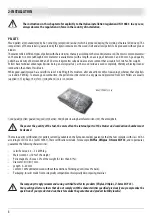
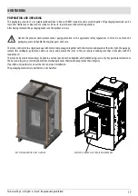
INTENDED USE

The product only works with wood pellets and must be installed indoors.

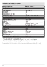
PRODUCT PERFORMANCE CHECKS.

All our products undergo ITT tests carried out by a notified laboratory (system 3) and in accordance with (EU) regulation number 305/2011 

“Construction products”, according to standard EN 14785:2006 (pellets) and “Machinery Directive” EN 303-5 (boilers).

In the case of tests for any market surveillance or inspections by third parties, please consider the following warnings:

• 

to reach the declared performance levels, the product must perform an operating cycle of at least 15/20 hours beforehand

• 

use the average draught of the combustion smoke specified in the “technical product features” table

• 

the type of pellets used must comply with current EN ISO 17225-2 regulations

• 

the amount of fuel may vary according to the length and calorific value of the fuel. This may require some adjustments to stay in line 

with the hourly consumption specified in the “technical product features” table. A1 pellets ensure an overall calorific value within 

tight margins compared to the test pellets used. However, size considerably influences performance, so on average it must not be 

less than 24 mm long and with a 6mm diameter

• 

in the case of a wood-burning product, check the correct residual moisture content of the fuel, which must not be less than 12% or 

more than 20%. As the moisture increases, different combustion air settings are required. The settings are to be carried out via the 

combustion air register, thereby modifying the mixture between primary and secondary air.

• 

it is necessary to check the operation of devices that can affect performance (for example air fans or electrical safety devices) in case 

of damage due to handling.

• 

maximum performance can be achieved at the maximum flame and ventilation power.

• 

strictly comply with the withdrawal points specified in regulations both in terms of emissions and temperature.

WARRANTY CONDITIONS

The company guarantees the product, 

with the exception of elements subject to normal wear

 (listed on the following page), for a 

period of 

2 (two) years 

from the date of purchase attested by:

• 

a document to serve as proof of purchase (invoice and/or receipt) that shows the name of the vendor and the date on which the 

purchase was made;

• 

forwarding of the completed warranty certificate within 8 days of purchase;

Furthermore, in order for the guarantee to be valid, the device must be installed and calibrated by qualified personnel, and where 

necessary, the user must be issued with a declaration of conformity and correct functioning of the product.

We recommend testing the product before completion with the relative finishes (cladding, painting of walls, etc.).

Installations that do not meet the current standards, improper use and lack of maintenance as expected by the manufacturer, void the 

product warranty.

The warranty is valid on the condition that the instructions and warnings contained in the user and maintenance manual are observed, 

and therefore the product is used correctly.

Содержание MALVA MULTIAIR 10 UP! S1

Страница 1: ...INSTALLATION GUIDE EN PELLET STOVE MALVA MULTIAIR 10 UP S1 PART 1 REGULATIONS AND ASSEMBLY Instructions in English...

Страница 2: ...S 17 4 UNPACKING 19 5 FITTING THE METAL HOUSING 22 6 RIGHT CONTROL PANEL OPENING 27 7 CONTROL PANEL ASSEMBLY FOR LEFT OPENING 28 8 OPENING THE DOOR OF THE FIREBOX 38 9 CONNECTIONS TO ADDITIONAL DEVICE...

Страница 3: ...By system we intend Stove Flue Air vent REVISIONSTOTHE PUBLICATION The content of this manual is strictly technical and the property of RED No part of this manual may be translated into other languag...

Страница 4: ...hopper The instructions provided in this manual must always be complied with to ensure the product and any electronic appliances connected to it are used correctly and accidents are prevented This ap...

Страница 5: ...n The doors covers on the appliance must remain closed when it is not used The product must be powered by an electrical system that is equipped with an effective earthing device Switch the product off...

Страница 6: ...f the product willrestandprovidesuitableinsulationifitismadeofflammablematerial e g wood fitted carpet or plastic Live electrical parts only power the product once it has been fully assembled Disconne...

Страница 7: ...ll calorific value within tight margins compared to the test pellets used However size considerably influences performance so on average it must not be less than 24 mm long and with a 6mm diameter in...

Страница 8: ...himneys flues or parts of the system affecting the appliance damagecausedbytamperingwiththeappliance atmosphericagents naturaldisasters vandalism electricaldischarges fires faults in the electric and...

Страница 9: ...uired to separate this equipment and or thebatteriesoraccumulatorsincluded fromothertypesofwasteandtakethemtothelocalcollectioncentre Thedistributorcanbeasked to collect the waste electrical and elect...

Страница 10: ...lets is around 4 9 kW kg To ensure good combustion the pellets must be stored in a dry place and protected from dirt Pellets are usually supplied in 15 kg bags therefore storing them is very convenien...

Страница 11: ...tallation of the appliance must ensure easy access to clean the appliance itself the smoke outlet pipes and the flue It is forbidden to install the stove in rooms with a fire hazard Installation in st...

Страница 12: ...as modern heating appliances have high efficiency with cooler flue gasses and consequently less draught it is therefore essential that the flue is built up to standard and always kept in perfect worki...

Страница 13: ...educe smokecooling Itshouldbeseparatedfromcombustibleorflammablematerialswithanairgaporinsulatingmaterials checkthedistance specified by the manufacturer of the fireplace according to EN1443 The chimn...

Страница 14: ...zed in accordance with the general method of calculation of UNI EN13384 1 or other proven efficiency methods Below is a list of some flues available on the market AISI 316 steel chimney with doublecha...

Страница 15: ...s critical to the safety of the system CHIMNEYPOT Thechimneypotisacrucialelementfortheheatingappliancetoworkproperly werecommendawindproofchimneypot A seeFigure7 The area of the opening for smoke extr...

Страница 16: ...stoves etc which could cause a depression in the room Make sure that with all appliances on the pressure drop between the room and the outside does not exceed the value of 4 Pa also for Oyster applia...

Страница 17: ...h with 1 accessible 90 bend 6 5 metres Maximum length with 3 accessible 90 bends 4 5 metres Maximum number of accessible 90 bends 3 Horizontal sections minimum slope 3 4 metres Use smoke ducts with a...

Страница 18: ...um safety distances from combustible materials The previous rules also apply for holes made in walls 2 Oldflue minimumpipe 100mmwiththeinclusionof an external access door for chimney cleaning 3 Extern...

Страница 19: ...54 525 80 253 96 157 172 313 60 60 80 1045 49 17 3 DRAWINGS ANDTECHNICAL FEATURES Technical Dept All rights reserved Reproduction prohibited DRAWINGS AND CHARACTERISTICS STOVE DIMENSIONS MALVA MULTIA...

Страница 20: ...iameter 6 mm and size 3 40 mm Pellet hourly consumption Min 0 5 kg h Max 2 3 kg h Autonomy At min 43 h At max 9 h Heatable volume m3 215 40 246 35 287 30 Combustion air inlet 50 mm Smoke outlet 80 mm...

Страница 21: ...d handle the majolica parts with care Thestoveisdeliveredinasinglepackagewithmetalsidespackagedtogetherwiththestructureandplacedattheside Openthepackage remove the cardboard polystyrene and any straps...

Страница 22: ...u s 20 4 UNPACKING To remove the stove from the pallet you must remove the two screws u and plate s from the stove s foot There are four brackets s REMOVING THE FASTENING BRACKETS...

Страница 23: ...ecting pipe If the stove needs to be connected to an outlet pipe which goes through the rear wall to connect to the flue take utmost care to make sure that the joint is not forced If the stove smoke o...

Страница 24: ...et with the stove structure Taketheboxwiththecladdingsandpreparethemforinstallation Themetalpartsaretobeassembledtothestructureinaccordancewith the indications on the following pages Live electrical p...

Страница 25: ...t All rights reserved Reproduction prohibited Take metal side B and insert rubber pad D and bumpers C 2 D 2 C on each upper part of panel B in the upper part Insert the two bumpers C in the lower part...

Страница 26: ...4 5 FITTINGTHE METAL HOUSING Now take panel B and insert the z holes in the v hooks on the stove frame At the top fasten panel B to structure with the two screws E Proceed in the same way also for the...

Страница 27: ...HOUSING Technical Dept All rights reserved Reproduction prohibited Then assemble the A top on the frame by placing it over the stove in its adjustable dampers To strengthen tightness the A top is also...

Страница 28: ...cleaning of the stove it is necessary to remove the F decorative panel With the stove without top A remove the two k screws in the top part from the j hole in the frame in the bottom part raise the C...

Страница 29: ...shownbelow Takethe s handlewith your hand and pull to the right until panel T is completely extracted There is a limit switch in the panel guide so there is no danger of it falling Ifitisnotpossibleto...

Страница 30: ...tion Theelectricalconnection changeandfunctioningoperationsmustonlybecarriedoutbyauthorisedand qualifiedpersonnel With stove off and disconnected from current proceed as follows remove the T panel by...

Страница 31: ...Technical Dept All rights reserved Reproduction prohibited disconnect piston pin c the T panel is now completely detached from the stove put it in a safe place until next use remove screw d and bushin...

Страница 32: ...v 30 7 CONTROL PANEL ASSEMBLY FOR LEFT OPENING remove the two v screws that secure the panel support to the stove...

Страница 33: ...production prohibited now cable C will be connected in board to the stove but disconnected from the panel panel T will be completely disconnected the panel support Z will be independent from the stove...

Страница 34: ...ROL PANEL ASSEMBLY FOR LEFT OPENING from block H remove cap W from the left by removing the two k screws remove handle s from the right now insert cap W on the right and tighten it with screws k also...

Страница 35: ...s reserved Reproduction prohibited from the cart with guide G closed remove screw o on the right while with guide G open remove the two screws p for right opening the guide block G can be detached fro...

Страница 36: ...e it from the hole on the back panel the cable C then remains secured to the plate M see the image below remove the knockout hole s in the left part of the stove back panel pass the free end of the ca...

Страница 37: ...ENING Technical Dept All rights reserved Reproduction prohibited secure the plate M once again using the two screws x on the left rotate the guide position to be able to extract the panel on the left...

Страница 38: ...o p G p G H G 36 7 CONTROL PANEL ASSEMBLY FOR LEFT OPENING fix guide G again using screw o with guide closed and the two screws p with guide open block H is pre assembled as is guide block G...

Страница 39: ...CONTROL PANEL ASSEMBLY FOR LEFT OPENING Technical Dept All rights reserved Reproduction prohibited take screws y and block guide G to block H take the whole block and secure it to the stove with the...

Страница 40: ...T c s d b 38 7 CONTROL PANEL ASSEMBLY FOR LEFT OPENING take panel T and connect the two piston pins c and s insert panel T in its seat position bushing b and screw d for the panel limit switch...

Страница 41: ...reserved Reproduction prohibited DOOR OPENING To open the stove door fit the cold handle f into the hole in the handle and pull it towards you Attention Thefireboxdoormustbeclosedproperlyforthestoveto...

Страница 42: ...WIFI INTERFACE OPTIONAL Install theWeb Wi Fi using the holes on the back of the product and follow the instructions on the product itself Attention the APP REDWIFI Easy is available in the Play Store...

Страница 43: ...s reserved Reproduction prohibited ASH PAN ACCESSORY It is possible to purchase an ash pan K optional to be inserted in the lower compartment to help ash cleaning and collection Open the stove firebox...

Страница 44: ...dcomeincontactwithflammablesurfacesorpartsthat are affected by heat e g change in shades wiring ducts plasterboard etc Moreover persons and animals must beprotectedfromaccidentalorintentionalcontact I...

Страница 45: ...put for safety purposes and to prevent the rear wall from being hit directly by the hot air flow generating halos blackeningorevendangerousheatinginthecaseofflammablewalls Whenpositioningthestoveneara...

Страница 46: ...ove mitten that comes with the stoveitself Whenloading donotletthepelletbagcomeintocontactwithhotsurfaces Neverremovetheprotectiongridinsidethehopper No other type of fuel other than pellets is to be...

Страница 47: ...r connecting the power cable to the back of the stove turn the switch at the back to position I The luminous switch button will light up The switch on the back of the stove is used to power the system...

Страница 48: ...07 03 2019 REV 1 8901874800 Via La Croce n 8 33074Vigonovo di Fontanafredda PN ITALY Telephone 39 0434 997200 Internet www red365 it e mail info red365 it...

Отзывы: