background image

COPYRIGHT © 2013 RED.COM, INC  

RED DSMC OPERATION GUIDE

   955-0020_V5.1, REV-D  

|

   48


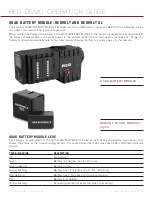
Magnify

: Tallies 1:1 if magnify is selected


Media Status

: Media location and remaining media capacity in %


Power

: Indicates D.C supply voltage or % of remaining battery capacity Including current supply voltage


Project Frame Rate

: Current project TIME BASE 


REDCODE

: REDCODE setting


Resolution

 Recording Resolution


RIG

: Indicates 3D rig metadata is present


Shutter Speed

: Exposure time or shutter angle


Shutter Sync

: Indicates sensor shutter sync status


TC

: Indicates presence of valid SMPTE timecode signal


Timecode

: Current timecode value 


White Balance

: Color Temp


Wireless Status

: Displays signal strength when connected wirelessly

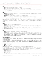
NAVIGATE GRAPHICAL USER INTERFACE

The primary method to navigate Menus is via the Scroll Wheel on the REDMOTE or DSMC SIDE HANDLE. Press 

Enter to open the menu, and then rotate the Scroll Wheel clockwise to move right, counter clockwise to move 

left. However, the Left and Right direction Navigation Keys (REDMOTE or DSMC SIDE HANDLE) or Adjustment 

Ring (DSMC SIDE HANDLE) may also be used for this purpose. 
The Up Navigation Key selects the Advanced Settings menu when pressed (if parameter has an Advanced Set-

tings menu).
As an example, position the Cursor under the Shutter Speed (24 FPS) icon and press the UP Direction Key to 

access advanced adjustment values for Shutter Speed.

NAVIGATE MENUS WITH TOUCHSCREEN LCD

If operating a Touchscreen LCD, camera menu navigation may be made through finger gestures.


To adjust a parameter value, simply touch it, and then swipe the finger left/right to adjust its value. 


To access an advanced parameter settings display, press and hold down on the parameter icon, then click 

Advanced...


Touch anywhere outside the overlay windows to enter the value changes and to hide the sub-menus.

TOUCHSCREEN SHORTCUTS

The bottom portion of the touchscreen contains shortcuts to the most-used camera screens.

ACCESS SOFT KEYS

User-programmable Soft Keys A-D and 1-4 may be accessed by tapping the left or right regions of the touch-

screen. 

Содержание Dragon

Страница 1: ...EPIC SCARLET V5 1 DRAGON MYSTERIUM X RED COM RED DSMC O PERAT ION GU IDE ...

Страница 2: ...back 95 Power 96 HDR Menu 97 Focus Menu 98 Presets 103 Chapter 7 Upgrade DSMC Firmware 106 Verify Current Camera Firmware 106 Upgrade Procedure 106 Chapter 8 Manage Digital Media 108 Overview 108 Format Media 108 Metadata 109 Clip Naming Conventions 110 Media Capacity Remaining Status 110 Eject Media from Camera Unmount 110 Offload Media to your Computer 111 Erase Media 111 Media Menu 112 Chapter ...

Страница 3: ...Media Attached 151 Recording Halted Record Error Shutdown 151 Preset Could Not Be Applied 151 Camera Cannot Be Paired to REDMOTE 151 Cannot See Menus on LCD Touchscreen 151 Appendix H Technical Specifications 152 EPIC DRAGON 152 EPIC MYSTERIUM X 154 SCARLET DRAGON 156 SCARLET MYSTERIUM X 158 DSMC Brain Dimensions 160 Appendix I Menu Map 165 ...

Страница 4: ... in terference CAUTION Exposure to Radio Frequency Radia tion The device shall be used in such a manner that the potential for hu man contact is minimized This equipment complies with FCC radiation exposure limits set forth for an uncontrolled environment This equipment should be installed and operated with a minimum distance of 20 cm between the radiator and your body CAUTION Regulations of the F...

Страница 5: ...ANCE Usage Restrictions Geographic Area Where Restriction Applies France For mainland France 2 400 2 4835 GHz Channels 1 16 authorized for indoor use 2 400 2 454 GHz Channels 1 10 authorized for outdoor use Restrictions d utilisation Zone géographique où les restrictions s appliquent France Pour la France métropolitaine 2 400 2 4835 GHz Canaux 1 à 16 autorisé en usage intérieur 2 400 2 454 GHz can...

Страница 6: ... 0 C to 40 C 32 F to 104 F Storage range 20 C to 50 C 4 F to 122 F If there are any performance issues with your camera or acces sories when operating within this temperature range please file a support ticket on support red com The DSMC SIDE HANDLE SIDE SSD Module Rear Modules and Lens Mount are NOT HOT SWAPPABLE meaning you can not remove or install them while the camera is powered on Be fore in...

Страница 7: ...leading specs in resolution frame capture dynamic range and color science the RED DRAGON sensor raises the bar for digital still and motion cameras again MYSTERIUM X SENSOR The MYSTERIUM X sensor is specifically designed for use with the RED DSMC BRAIN and in the EPIC it pro vides variable frame rate imaging at up to 95 FPS at 5K FF resolution and up to 400 FPS at 1K WS resolution Native color bal...

Страница 8: ...sly shoots two images of identical resolution and frame rate a normally exposed primary track A track and an underexposed secondary track X track whose exposure value reflects the additional stops of highlight protection desired For example if you select an HDR value of 2 and your primary track exposure is 1 48 sec the secondary track exposure will be 2 stops under or 1 192 sec The ISO and apertur...

Страница 9: ...ls are routed via a high quality pre amplifier and soft clip analog limiter in order to achieve the de sired audio reference recording level and maximize dynamic range To assist with audio reference level setup the camera provides a color coded Audio Level Meter in the graphi cal user interface Meter range is 36 dBu to 20 dBu 56 dBFS to 0 dBFS with audio input type reference level and audio input ...

Страница 10: ...ications where use of an attached RED EVF or RED LCD is not desired such as when working on a crane the VIEWFINDER MENU output can be transferred to the HD SDI or HDMI outputs supporting remote camera monitoring up to 200 ft away RED TOUCH LCD The RED TOUCH LCD pixel progressive scan color display allows you to view your image and navigate through menu settings using touchscreen functionality For ...

Страница 11: ...ng conditions the REDMOTE should operate for up to 8 hours without requiring a re charge and support a wireless communication range of approximately 50 ft SMPTE TIMECODE Time Code TC is a SMPTE timecode track that synchronizes to the camera s high precision internal clock or if operated in Jam Sync mode referencing an externally supplied SMPTE master timecode signal TC is a sequential code that is...

Страница 12: ...SSD MODULE rear modules and Lens Mount are NOT HOT SWAP PABLE meaning you cannot remove or install them while the camera is powered on Before installing or remov ing any of these accessories you MUST power down the camera Failure to do so may result in damage to the accessory and or camera brain that will not be covered under warranty BRAIN EPIC Brain 02 COMPONENTS AND MODULES ...

Страница 13: ...nning on battery Yellow flashing Power present 5 10 minutes of battery time left Red flashing Power present less than 5 minutes of battery time left Record Status LED REC Off No media present Green Ready to record Red Recording Red slow flashing Recording 25 media left Red fast flashing Recording 5 media left Yellow Finalizing Power Status LED PWR and Record Status LED REC Both green flashing Firm...

Страница 14: ...wered on Before installing or remov ing the RED MINI MAG SIDE SSD or DSMC 1 8 SSD SIDE MODULE you MUST power down the camera Failure to do so may result in damage to the module or DSMC that will not be covered under warranty RED MINI MAG SIDE SSD The RED MINI MAG SIDE SSD attaches to the DSMC so that you can mount a RED MINI MAG to your camera The RED MINI MAG SIDE SSD has the same EVF LCD LEMO co...

Страница 15: ...ng SSDs mounts to the DSMC 1 8 SSD SIDE MODULE REDMAG 1 8 SSD 48GB REDMAG 1 8 SSD 64GB REDMAG 1 8 SSD 128GB REDMAG 1 8 SSD 256GB REDMAG 1 8 SSD 512GB SIDE SSD MODULE CONTROLS The RED MINI MAG SIDE SSD and DSMC 1 8 SSD SIDE MODULE have the control buttons described in the tabled below CONTROL DESCRIPTION User Key 1 Programmable key User Key 1 2 Press Eject Media User Key 2 Programmable key User Key...

Страница 16: ...1 8 SSD SIDE MODULE have the LED described in the tabled be low LED COLOR FLASHING DESCRIPTION Media Indicator LED Off No media present Green Ready to record Red Recording Red slow flashing Recording 25 media left Red fast flashing Recording 5 media left Yellow Finalizing Yellow flashing Accessing media for example when formatting ...

Страница 17: ...ng A battery compartment for one REDVOLT battery An LCD display that shows key camera parameter values Many programmable user keys and buttons For a full list of all DSMC SIDE HANDLE user keys and their default actions go to Default Key Functions on page 142 DSMC SIDE HANDLE Front left DSMC SIDE HANDLE Rear right DSMC SIDE HANDLE Top ...

Страница 18: ... the camera is powered on Before installing or removing the DSMC SIDE HANDLE you MUST power down the camera Failure to do so may result in damage to the DSMC SIDE HANDLE or DSMC that will not be covered under warranty 1 Power down the camera 2 Rotate the thumbscrew downward until the DSMC SIDE HANDLE detaches from the camera body 3 Pull the bottom of the DSMC SIDE HANDLE away from the brain to dis...

Страница 19: ...ntains appropriate operating temperature REAR SSD MODULE The REAR SSD MODULE secures onto the back of the DSMC brain to serve as a rear location for recording onto 1 8 REDMAG SSD media QUAD BATTERY MODULE The QUAD BATTERY MODULE holds up to four REDVOLTs or two REDVOLT XLs PRO I O MODULE REAR SSD MODULE ...

Страница 20: ...uctions in this section to install and remove DSMC modules INSTALL MODULE ADAPTOR Use the instructions in this section to install the MODULE ADAPTOR REQUIRED TOOL T20 Torx driver You must install a MODULE ADAPTOR to the back of the camera brain before you install a DSMC module MODULE ADAPTORs are sold separately from the DSMC modules 1 Power down the camera 2 Remove the REDMOTE if attached QUAD BA...

Страница 21: ... INSTALL THE 1 ADAPTOR MODULE Use the instructions in this section to install the 1 ADAPTOR MODULE WARNING DSMC modules and adaptors are NOT HOT SWAPPABLE meaning you cannot remove or install the modules while the camera is powered on Before installing or removing modules you MUST power down the camera Failure to do so may result in damage to the modules or DSMC that will not be covered under warr...

Страница 22: ...the HDMI connector into the DSMC BRAIN 5 Use a T20 Torx driver to tighten four 4 captive screws Tighten screws in a cross pattern approximately two turns each DO NOT FULLY TIGHTEN 6 Fully tighten four 4 screws in a cross pattern DO NOT OVERTIGHTEN Install 1 ADAPTOR MODULE Insert the HDMI Connector to DSMC BRAIN Tighten the screws in an X pattern ...

Страница 23: ...x driver 1 Insert the lip at the top of the module into the recess at the top of the MODULE ADAPTOR 2 Rotate the module down flush with the rear of the MODULE ADAPTOR 3 While applying steady pressure to hold the module against the MODULE ADAPTOR use a T20 Torx driver to rotate the lock on the MODULE ADAPTOR clockwise to the Lock position in order to secure the module REMOVE DSMC MODULE AND ADAPTOR...

Страница 24: ...IDE 955 0020_V5 1 REV D 24 4 Remove the module from the MODULE ADAPTOR 5 Use a T20 Torx driver to loosen the screws attaching the MODULE ADAPTOR to the camera brain 6 Remove the MODULE ADAPTOR from the camera brain Remove Module Loosen MODULE ADAPTOR ...

Страница 25: ...era is powered on Before installing or removing modules you MUST power down the camera Failure to do so may result in damage to the modules or DSMC that will not be covered under warranty REQUIRED TOOL T20 Torx driver 1 Power down the camera 2 Using a T20 Torx driver loosen four 4 captive mounting screws attaching the 1 ADAPTOR MODULE to the DSMC BRAIN 3 Disconnect the HDMI connector from the DSMC...

Страница 26: ...APTOR MODULE WARNING The MODULE ADAPTOR IS NOT compatible with the 1 ADAPTOR MODULE 1 ADAPTOR MODULE The 1 ADAPTOR MODULE mounts onto the back of a DSMC BRAIN and provides power and support for an additional RED EVF LCD The 1 ADAPTOR MODULE also includes an AUX power port for 4 pin third party ac cessories Other 2 pin accessories are also compatible when using a 4 PIN TO 2 PIN ADAPTOR CABLE WARNIN...

Страница 27: ... default Auxiliary Power Output setting will be turned ON Thereafter the last Auxiliary Power Output setting is restored MULTIPLE CONTROL SURFACES The DSMC BRAIN may only utilize one control surface LCD at any given time If multiple RED Touch LCDs are attached to the camera BRAIN and the 1 ADAPTOR MODULE you may prioritize the primary control surface in the menu settings at Settings Display Monito...

Страница 28: ...in based accessories Micro HDMI to HDMI Adaptor Micro HDMI to Stan dard HDMI HDMI video connection from DSMC BRAIN to support auxiliary EVF LCD attachment NOTE The 4 PIN TO 2 PIN ADAPTOR CABLE converts 4 pin power into a 2 pin female LEMO connection en abling support for 2 pin based accessories from the 1 ADAPTOR MODULE or PRO I O MODULE NOTE The Micro HDMI to HDMI Adaptor is field replaceable 1 A...

Страница 29: ...s to the mounting locations on the top of the 1 ADAPTOR MODULE Use the following instructions to replace DSMC fan hood scoop 1 Use a T8 Torx driver to remove the four 4 screws 2 Lift off the old hood scoop 3 Place the replacement hood scoop on the camera Align hood scoop screw holes with the threaded holes on top of the camera 4 Insert and lightly tighten the four screws in a cross pattern DO NOT ...

Страница 30: ...m the camera or rearmost module and pro vide wireless remote control of the camera over proprietary REDlink protocol For complete details about how to use the REDMOTE go to REDMOTE Operation on page 118 For a full list of all REDMOTE user keys and their default actions go to Default Key Functions on page 142 IMPORTANT For the REDMOTE to operate properly ensure that both REDMOTE and DSMC firmware a...

Страница 31: ...ition lightweight viewfinder that aligns quality performance with compact form factor Resolution 1280 wide x 784 high full color Contrast Ratio 1000 1 typical Available Diopter Range 2 0 to 5 0 I BOMB EVF OLED The RED BOMB EVF OLED brings advanced OLED technology into the field providing truer blacks and more color accurate images Resolution 1280 wide x 1024 high full color Contrast Ratio 1000 1 t...

Страница 32: ...heir default actions go to Default Key Functions on page 142 TOUCHSCREEN LCD GESTURES Tap Tap on an icon to bring up a quick adjustment display Double Tap If the monitor is in Clean mode changes to Overlay mode Hold Touch and hold on an icon to bring up an advanced interface display Slide When a menu or drop down menu is open touch and slide to increment a value Pinch Touch with two fingers then o...

Страница 33: ...vel axis has a total range of adjustment of approximately 360 180 clockwise or coun terclockwise from the nominal rear facing display orientation The range of adjustment for the tilt axis is ap proximately 180 At the end of the adjustment range are internal hard stops for both axes Once the swivel or tilt hard stops have been reached IMMEDIATELY STOP APPLYING FORCE TO THE LCD Continuing to apply f...

Страница 34: ...pical operating conditions a REDVOLT battery will run the camera and accessories for about 30 min utes and a REDVOLT XL battery will run the camera and accessories for about 90 minutes POWER DRAW Power draw is prioritized as follows when multiple power sources are available to the camera 1 DC Voltage or Brick 2 Battery module batteries 3 REDVOLT battery in the DSMC SIDE HANDLE POWER SOURCES DSMC S...

Страница 35: ... While still pressing the red retainer up insert a REDVOLT battery until it is fully seated and the retainer clicks into place 4 Close battery door REMOVE REDVOLT FROM DSMC SIDE HANDLE 1 Press the battery door release button at the top of the DSMC SIDE HANDLE The battery door opens 2 Press up on the red retainer 3 While still pressing the red retainer up remove the REDVOLT battery from the battery...

Страница 36: ...e automatically selects the next lowest charged battery to supply power to the camera QUAD BATTERY MODULE LEDS Each battery compartment of the QUAD BATTERY MODULE has an LED above the battery eject button that shows the status of the corresponding battery The table below describes what each LED color flashing mode means COLOR FLASHING DESCRIPTION Off No battery Green Battery is charged but is not ...

Страница 37: ...ttery pops out remove the battery from the QUAD BATTERY MODULE QUICKPLATE MODULE The QUICKPLATE MODULE attaches to a 1 ADAPTOR MODULE or MODULE ADAPTOR to provide RED BRICK power to your DSMC Unlike the BACKPACK QUICKPLATE and BACKPACK QUICKPLATE SHORT this prod uct does not require the use of a Lemo cable or BACKPACK BASEPLATE This allows you to mount your RED BRICK onto the back of your camera b...

Страница 38: ...re pulling 2 0 A out of one port you can pull up to 1 8 A out of the other port When connecting a cable to an auxiliary connector align the key and red mark on the auxiliary connector with the corresponding key on the cable connector PIN DESCRIPTION 1 Ground 2 12VDC INSTALL QUICKPLATE MODULE The QUICKPLATE MODULE attaches to the DSMC brain the same way that the other DSMC modules attach For more i...

Страница 39: ...required for use of the BACKPACK QUICKPLATE and the BACKPACK QUICK PLATE SHORT BACKPACK QUICKPLATE CONNECTOR The BACKPACK QUICKPLATE has one D tap connector for auxiliary accessories 70 W max PIN DESCRIPTION 1 Ground 2 12VDC BACKPACK QUICKPLATE SHORT CONNECTORS The BACKPACK QUICKPLATE SHORT has two 1B 2 pin auxiliary connectors that provide a maximum com bined output of 3 8 A For example if you re...

Страница 40: ...wise by 2 3 turns 3 Slide the BACKPACK QUICKPLATE dovetail into the BACKPACK BASE PLATE so that the V Mount on the BACKPACK QUICKPLATE is facing away from the DSMC 4 Secure the BACKPACK QUICKPLATE by turning the BACKPACK BASE PLATE wingnut clockwise until it stops turning do not over tighten 5 Slide the RED BRICK onto the back of the BACKPACK QUICKPLATE so that it fits into the V Mount on the back...

Страница 41: ... plug the module in via the 2B TO 1B POWER ADAP TOR CABLE P N 790 0138 4 pin XLR DC power sources may be used with the camera via the XLR POWER CABLE P N 790 0165 POWER STATUS The power status of each power source displays on the Power In screen To view the Power In screen go to Menu Power Power In POWER UP 1 Attach a power source to the DSMC For more information about the different power sources ...

Страница 42: ...automatically powers down if the supply voltage drops to 11 5 Volts Use either of the following ways to power down the DSMC Go to Menu Power and select Shutdown Press and continue to hold the Power Record button in its fully depressed position until the Shutting Down notification shows on the display ...

Страница 43: ... input selection and levels Cal T E Indicator of relative change in sensor temperature and exposure since your last calibration Clip Level Bar Relative number of RAW pixels near clip Clip Meter RGB sensor RAW clipping status Cursors Reference cursors Safe Action Safe Title Picture Center Grid Overlay Drop Indicates if any frames were dropped during recording of the clip F Stop Functional when opti...

Страница 44: ...re temperature in that order xx xxC Timecode Current timecode value White Balance Color Temperature The GUI is broken down into the following three main sections the Upper Status Row the Live Action Area and the Lower Status Row On VIEWFINDER output s all three sections are visible on PREVIEW outputs only the Live Action Area and associated graphic overlays are visible On PROGRAM outputs none of t...

Страница 45: ... DSMC NIKON MOUNT AND LENS When a DSMC Canon Mount or a DSMC Nikon Mount is installed with an electronically supported lens at tached the Focal Length and Focal Distance is displayed on the LCD EVF and external monitors When AF is set to Manual or Confirm mode the focus distance displays as a pair of Near Far distances When it is in AF mode a single estimated Focus distance is displayed The focal ...

Страница 46: ...cked to and the sensor timing is also locked to it LAN LAN Gray External control of the camera is not currently enabled LAN Yellow If the LAN icon is yellow you will see the message For reliable external control over Ethernet your camera s hardware may need to be upgraded Please contact your Bomb Squad representative If you see this message you will not be able to control the camera externally Ple...

Страница 47: ...ple if the bar is about 1 4 of the total height this would indicate approximately 1 8 of the total pixels in the image are at an ex posure level at risk of clipping and may not be recoverable by lowering ISO or FLUT values in post production DSMC SIDE HANDLE As you navigate and adjust settings in the Basic Menus they will be reflected on the DSMC SIDE HANDLE LCD display The display elements includ...

Страница 48: ...clockwise to move left However the Left and Right direction Navigation Keys REDMOTE or DSMC SIDE HANDLE or Adjustment Ring DSMC SIDE HANDLE may also be used for this purpose The Up Navigation Key selects the Advanced Settings menu when pressed if parameter has an Advanced Set tings menu As an example position the Cursor under the Shutter Speed 24 FPS icon and press the UP Direction Key to access a...

Страница 49: ...sor frame rate also referred to as the capture frame rate The sensor frame rate is the number of frames per second FPS that are recorded The sensor frame rate is different from the project time base which is the rate at which the footage will be played back The default sensor frame rate is 23 98 FPS or the selected project time base when it is a value other than 23 98 FPS or 24 FPS Select the Adva...

Страница 50: ...creases the amount of time during which light falls on the sensor increasing expo sure and motion blur on any objects moving within the frame Increasing shutter speed shortens the amount of time during which light falls on the sensor decreasing exposure and motion blur on objects moving within the frame From the Exposure menu you can set the exposure value as a shutter speed 1 xx sec or a shutter ...

Страница 51: ... about the available resolutions for your camera and the advanced format settings go to Format on page 71 REDCODE Select the target REDCODE compression ratio for your project If the camera is able to achieve the target compression ratio the compression ratio displays in white If the camera is unable to achieve the target compression ratio the compression ratio displays in yellow The current compre...

Страница 52: ...e REDCODE and frame rate capabilities in the table below are based on recording to a 128GB RED MAG CAPTURE FRAME RATE FPS FORMAT 12 24 25 30 40 48 50 60 72 75 90 96 100 120 150 175 210 250 288 300 6K 3 5 6 7 9 10 11 13 15 16 6K 2 1 3 5 5 6 8 10 10 12 15 15 6K WS 2 4 5 5 7 8 9 10 12 13 15 16 17 6K HD 3 5 5 6 8 9 10 11 14 14 5 5 K 3 5 5 6 7 9 9 11 13 13 5 5K 2 1 2 4 5 5 7 8 9 10 12 13 15 5 5K WS 2 4...

Страница 53: ...2 2 2 2 3 3 3 4 4 4 5 5 6 7 8 3K WS 2 2 2 2 2 3 3 3 4 4 4 5 5 6 7 8 3K HD 2 2 2 2 2 3 3 3 4 4 5 5 5 6 8 3K 3 2 2 2 2 3 3 4 4 5 5 6 7 7 7 9 3K 4 3 2 2 2 2 3 4 4 4 5 5 6 7 7 8 3K 5 4 2 2 2 3 3 4 4 5 6 6 7 7 8 2 5K 2 2 2 2 2 2 2 3 3 3 4 4 4 5 6 7 2 5K 2 1 2 2 2 2 2 2 2 3 3 3 4 4 4 5 6 7 2 5K WS 2 2 2 2 2 2 2 2 3 3 3 3 3 4 5 6 7 2 5K HD 2 2 2 2 2 2 2 3 3 3 4 4 4 5 6 7 2 5K 3 2 2 2 2 2 2 2 3 3 3 4 4 4 ...

Страница 54: ...aximum avail able REDCODE compression ratio is 3 1 NOTE The REDCODE and frame rate capabilities in the table below are based on recording to a 128GB RED MAG CAPTURE FRAME RATE FPS FORMAT 12 24 25 30 40 48 50 60 72 75 90 96 100 120 150 175 210 250 288 300 400 5K 3 3 4 4 5 6 7 8 9 10 12 12 5K 2 1 3 3 3 4 5 6 6 8 9 9 11 12 12 5K WS 3 3 3 3 4 5 5 6 8 8 9 10 10 12 5K HD 3 3 3 4 5 6 6 8 9 9 11 12 5K ANA...

Страница 55: ...pression ratio the x of x 1 For example when your project format is 4K and your capture frame rate is 24 FPS the maximum avail able REDCODE compression ratio is 6 1 NOTE The REDCODE and frame rate capabilities in the table below are based on recording to a 128GB RED MAG CAPTURE FRAME RATE FPS FORMAT 12 24 25 30 40 48 50 60 72 75 90 96 100 120 5K 5 5K 2 1 5 5K WS 4 5K HD 5 5K ANA 3 4K 3 6 6 8 4K WS...

Страница 56: ...u to use different false color modes and display modes False color options are None Exposure Focus Video and Edge Display mode options are Magnify and RAW You can access the Tools menu the following ways Navigate to Settings Display Tools Press the Histogram in the lower left area of the on screen display For more information about the different false color modes check out the Exposure with RED Ca...

Страница 57: ...Group VIDEO Displays a multi color overlay that allows you to check the video level of the RGB monitor path calibrated to the SMPTE test signal and any outputs driven from that path such as HD SDI and HDMI When enabled the icon V displays in the Lower Status Group Color bands are based on the RGB levels of the video out signal that is the cooked look and not the RAW data so settings like ISO FLUT ...

Страница 58: ...osure with RED Cameras False Color Zebra Tools article available at www red com learn red 101 exposure false color zebra tools ENABLE ZEBRA INDICATORS 1 Select a Zebra check box 2 Select the low and high IRE values Each value range is 1 100 Zebra 1 Areas of the image exposed within the IRE range are indicated by diagonal lines at 45 Default is IRE 98 100 Zebra 2 Areas of the image exposed within t...

Страница 59: ... over it Auto Hide Menus Hides the menus top and bottom bars on the display When this option is disabled the video is scaled so that the menus are not overlaid on the video When this option is enabled the video is not scaled and you can bring up the menus on the LCD by pressing the Menu button on the DSMC SIDE HAN DLE or by tapping the screen This lets you have a control surface on a monitor witho...

Страница 60: ...abel LBL enter the Custom Text for that item 9 Click Add to return to the previous screen 10 Add all of the items to the overlay 11 After setting up your overlay select Create or Save The new overlay displays in the Camera list NOTE Except for the Custom Label LBL you can only add each element once If you add an element you have already added to the overlay the element will move to the new positio...

Страница 61: ...de the shutter time stays the same but the shutter angle changes This is the default Angle Relative Displays the exposure as an angle 1 360 degrees When you change the frame rate in this mode the shutter angle stays the same but the exposure time changes NOTE If the target you select is not currently achievable the shutter speed turns yellow which indicates that the camera is using the closest ava...

Страница 62: ... screen On Displays the effective ISO While the effective ISO is displayed on the main screen you should continue to follow standard exposure best practices and select your ISO based on the camera s native ISO Off Displays actual ISO This is the default RACK TARGET FOCUS Displays the focus distance of each rack point on the main screen when rack focus is enabled For more infor mation about rack fo...

Страница 63: ...t provides maximum color contrast with the scene you are shooting The default is White Opacity Set the guide opacity Available options are 0 25 50 75 and 100 RELATIVE TO FRAME GUIDE Only available on the Action Guide and Title Guide tabs Select this check box so that the guide is sized and positioned relative to and bounded by the Frame Guide instead of the record format GENERAL TAB You can enable...

Страница 64: ...the actual REDCODE RAW data being recorded COLOR You can adjust the following Saturation Adjusts color saturation Range is 0 0 monochrome to 4 0 super color Default is 1 0 Contrast Adjusts the overall contrast of the image Range is 1 0 flat to 1 0 max contrast Default is 0 0 Brightness Adjusts brightness without crushing highlights Available range is 10 0 to 10 0 Default is 0 0 Exposure Adjusts ex...

Страница 65: ...t you recorded with that legacy setting For more information about RED gamma settings check out the Understanding REDlogFilm and REDgamma article available at www red com learn red 101 redlogfilm redgamma COLOR TEMPERATURE Color temperature range is 1700 100 000 K with a default of 5600 K TINT Color temperature calculations assume a pure light source that may not be true in the specific scene the ...

Страница 66: ...is a value other than 23 98 FPS or 24 FPS PROJECT TIME BASE Defines the rate at which the footage will be played back When changing the project time base the sensor frame rate will default to the project time base but may be over ridden using the sensor frame rate controls The time base setting is displayed in the lower left corner of Viewfinder output s Multiple projects with differing time bases...

Страница 67: ...MAX FRAME RATE FPS 6K FF 82 81 3 5K WS 166 77 6K 2 1 84 73 3 5K HD 135 51 6K WS 100 21 3 5K 3 2 114 12 6K HD 83 12 3 5K 4 3 101 76 5 5K FF 87 43 3 5K 5 4 95 56 5 5K 2 1 92 34 3K FF 159 1 5 5K WS 109 19 3K 2 1 167 62 5 5K HD 87 43 3K WS 197 86 5K FF 95 69 3K HD 159 1 5K 2 1 100 83 3K 3 2 134 68 5K WS 119 08 3K 4 3 119 94 5K HD 95 69 3K 5 4 112 56 4 5K FF 107 06 2 5K FF 192 09 4 5K 2 1 112 94 2 5K 2...

Страница 68: ...TE FPS EPIC MYSTERIUM X MAX FRAME RATE FPS SCARLET MYSTERIUM X 5K FF 95 83 12 5K 2 1 100 83 12 5K WS 120 83 12 5K HD 95 83 12 5K 1 22 1 95 83 12 4K FF 120 83 30 4K WS 152 47 36 4K HD 120 83 30 3K FF 159 88 48 3K WS 200 88 60 3K HD 159 88 48 2K FF 239 67 60 2K WS 301 79 75 2K HD 239 67 60 1K HD 356 58 90 1K WS 400 120 EXPOSURE The Exposure screen allows fine control over the exposure value and perm...

Страница 69: ...EXPOSURE CONVERSIONS As you adjust any of these three parameters the camera automatically calculates the equivalent value in the other units but as a quick reference here are some common speeds and angles CONVERT SHUTTER SPEED TO SHUTTER ANGLE FOR 24 FPS Equivalent Degrees Shutter Speed x Frame Rate x 360 For example 1 48 x 24 x 360 8640 48 180 SHUTTER DEGREES SHUTTER DEGREES 1 32 270 1 120 72 1 4...

Страница 70: ...ime code from an external device connected to the time code connector on the camera brain External Rear Module Varies by device Uses the time code from an external device connected to the time code connector on a rear module such as the RED PRO I O MODULE TIME CODE AND HANC DATA The time code displayed becomes the primary time code HANC data while the other time code is sent as sec ondary SLATE Us...

Страница 71: ...me 6144 3160 6K 2 1 6K RAW 2 1 6144 3072 6K WS 6K RAW Wide Screen 6144 2592 6K HD 6K RAW HD 5568 3132 5 5K FF 5 5K RAW 5600 2960 5 5K 2 1 5 5K RAW 2 1 5600 2800 5 5K WS 5 5K RAW Wide Screen 5600 2360 5 5K HD 5 5K RAW HD 5280 2960 5K FF 5K RAW Full Frame 5120 2700 5K 2 1 5K RAW 2 1 5120 2560 5K WS 5K RAW Wide Screen 2 4 1 5120 2160 5K HD 5K RAW HD 4800 2700 4 5K FF 4 5K RAW 4608 2432 4 5K 2 1 4 5K ...

Страница 72: ...20 3K 4 3 3K RAW 4 3 2880 2160 3K 5 4 3K RAW 5 4 2880 2304 2 5K FF 2 5K RAW Full Frame 2560 1340 2 5K 2 1 2 5K RAW 2 1 2560 1280 2 5K WS 2 5K Wide Screen 2 4 1 2560 1080 2 5K HD 2 5K RAW HD 2400 1340 2 5K 3 2 2 5K RAW 3 2 2400 1600 2 5K 4 3 2 5K RAW 4 3 2400 1800 2 5K 5 4 2 5K RAW 5 4 2400 1920 2K FF 2K RAW Full Frame 2048 1080 2K 2 1 2K RAW 2 1 2048 1024 2K WS 2K RAW Wide Screen 2 4 1 2048 864 2K...

Страница 73: ...1 4K WS 4K RAW Wide Screen 2 4 1 4096 1708 22 12 9 22 23 96 4K HD 4K RAW HD 3840 2160 20 74 11 66 23 79 3K FF 3K RAW Full Frame 3072 1620 16 59 8 75 18 75 3K WS 3K Wide Screen 2 4 1 3072 1284 16 59 6 93 17 98 3K HD 3K RAW HD 2880 1620 15 55 8 75 17 84 2K FF 2K RAW Full Frame 2048 1080 11 06 5 83 12 50 2K WS 2K RAW Wide Screen 2 4 1 2048 854 11 06 4 61 11 98 2K HD 2K RAW HD 1920 1080 10 37 5 83 11 ...

Страница 74: ... as 5K Full Frame in EPIC MYSTERI UM X and 6K Full Frame in EPIC DRAGON show the full sensor area or full sensor height on the video display so Lookaround is either very limited or not possible in these formats AUDIO The AUDIO menu lets you configure the audio subsystem For more information about the DSMC audio system go to Audio Subsystem on page 114 RECORDING This menu lets you select and config...

Страница 75: ... SCARLET DRAGON This mode lets you program the current sensor frame rate to transition to a target sensor frame rate during recording 1 Select Speed Ramp Mode from the Recording Mode drop down menu 2 Use the Limit Recording to fields to set the recording to end at a predefined frame limit optional 3 Select a ramp target Ramp A B C D Each ramp target is tied to a specific Target Duration combinatio...

Страница 76: ...he original frames The resultant frame has an effective integration time that is equal to the current integration time multiplied by the number of frames For example if you select 16 as your Frames to Process value and set your exposure to 1 48 sec your result ing image has an effective integration time of 1 3 sec 16 x 1 48 Frame summing results in a final image that is brighter and possibly blurr...

Страница 77: ... DSMC SIDE HANDLE or REDMOTE moves you up one level in the menu tree Lock DSMC SIDE HANDLE Keys None of the DSMC SIDE HANDLE keys perform any actions when pressed unless you set up the exceptions below Record Key Remains Active When Locked If the DSMC SIDE HANDLE keys are locked the Record key continues to function when pressed Navigation Keys Remain Active When Locked If the DSMC SIDE HANDLE keys...

Страница 78: ...ng on all cameras With the exception of the None setting all command filtering happens on the receiver side of the communica tion link Name Enter a unique camera name to use in network communications The field is limited to eight 8 char acters Group Enter a group name if you want to identify the camera as a member of a group of devices For ex ample a group 3DRIG_A could include two cameras CAM_A_L...

Страница 79: ...r REDMOTES The DSMC scans for any REDMOTEs that are turned on with REDlink wireless enabled The available wireless REDMOTEs appear in the left panel Use the Pair and Unpair buttons to select and pair unpair REDMOTEs REDlink Enable When selected the DSMC produces a wireless signal Be sure to disable wireless in any setting in which the wireless signal could interfere with other devices such as in a...

Страница 80: ...Lower Status Row of the camera display has GEN and SYNC icons which change color based on the current genlock and sync statuses For information about what each color indicates go to Icon Behavior on page 45 PRO I O GPIO AND PRO I O SW Use the PRO I O GPI and PRO I O SW screens to assign General Purpose Inputs and Outputs GPIO on the PRO I O MODULE You can map I O actions to the GPIO and AUX connec...

Страница 81: ...emperature sensor warm up time fan speed and resulting fan noise When selecting a fan mode RED recommends that you take into consideration how each fan mode behaves and then select a fan mode that fits the needs of your project Regardless of your sensor type and target temperature you will get the best image quality by performing a black shading calibration at the temperature you want to use for y...

Страница 82: ...n compared to Auto mode ADAPTIVE PREVIEW QUIET RECORD Select a maximum bottom fan record speed and the standby mode fan speed self adjusts accordingly so that enough cooling is provided overall This mode maintains a lower fan noise level than Auto mode during record ing The default Maximum Record Speed is 50 The Maximum Record Speed range is 25 100 A slower speed setting results in a faster standb...

Страница 83: ...ne LENS LENS TAB The options you see on the Lens tab change based on the lens mount that s currently attached PL MOUNT Auto Detect PL Lenses By default this feature is disabled Detect Lens CANON AND NIKON LENS SETTINGS The settings below display when a DSMC Nikon Mount DSMC Canon Mount or DSMC Canon MOTION MOUNT is installed with a supported lens Aperture Enter the F stop value The range and defau...

Страница 84: ...port red com To save a LOG file follow the instructions below 1 Go to Settings Maintenance 2 Select Save Log The LOG file is saved as a txt file in the SSD root directory UPGRADE NOTE For more information on the firmware force upgrade procedure go Upgrade DSMC Firmware on page 106 You can check for upgrades for the following items Camera REDMOTE CALIBRATE You can perform a sensor calibration a mot...

Страница 85: ... cannot take off the lens put a lens cap on the lens Not all lens caps completely block IR Lens caps are made to protect the lens not necessarily to block light If possible use a dark room Just closing the iris is NOT sufficient 4 Ensure a properly formatted SSD is attached to the camera Even if you are not saving the calibration map to media an SSD is required to store the raw images during calib...

Страница 86: ...Map The calibration maps that are saved internally on the camera Factory This is the calibration map generated during the manufacturing process and is the default map User HS The user created calibration map Media The calibration maps that are on the media in the path shown for example S SSD calibration CALIBRATION MAP ACTIONS Set Set and apply the selected camera calibration map Delete Delete the...

Страница 87: ...ic lenses so that you can use features such as rack focus and autofocus with your lenses While the custom configuration files will not be as precise as the files for the lenses that are fully electronically supported by RED cameras the files will provide the F stop range and focal lengths so that you can electroni cally control the lens with the camera NOTE The camera may not be able to calibrate ...

Страница 88: ...D DSMC OPERATION GUIDE 955 0020_V5 1 REV D 88 Custom Lens Config Go to Settings Maintenance Calibrate Lens and select Create The lens calibration process for the current focal length starts and a progress bar displays Once the cali ...

Страница 89: ...EV D 89 bration process starts do NOT touch the lens as doing so may cause the lens to calibrate incorrectly 5 Click OK after the calibration file is created 6 To calibrate the next focal length follow the instructions below A Go to Settings Maintenance Calibrate Lens ...

Страница 90: ...th D Select Add Cal xx where xx is the current focal length NOTE If you calibrate a focal length that has already been calibrated the new files overrides the previ ous file The lens calibration process for the current focal length starts and a progress bar displays Once the calibration process starts do NOT touch the lens as doing so may cause the lens to calibrate incor rectly ...

Страница 91: ...ns on the camera after system restores and firmware upgrades VIEW AND MODIFY LENS CALIBRATION INFORMATION 1 Go to Settings Maintenance Calibrate Lens 2 Select the calibration file name in the Camera list and select Edit The following information displays Mount Type Focal Length F Stop Range Overall F stop range of lens Lens Status Calibrated Focal Lengths ...

Страница 92: ...nsferred to SSD so that you can build a library of lens calibration files or quickly copy a lens calibration file from one camera to another via SSD When exporting lens calibration files from camera to media the files are saved to a folder on the media called lens_cal Do NOT change the file name of the calibration file after you save it to media Export selected calibration file from camera to medi...

Страница 93: ...nsupported electronic lens at boot up De select this check box to disable the Unsupported Lens Found dialog box SELF TEST When selected allows you to perform a self test for the sensor and LCD Touchscreen ENABLE DISABLE SENSOR TEST PATTERN When selected enables disables the sensor test pattern White Screen To turn on select Enable Sensor Test Pattern To turn off select Disable Sensor Test Pattern ...

Страница 94: ...hanges from the cameras default settings The RED MOTE will also require paring to communicate wirelessly with the camera REDISCOVER Rediscovers all hardware and caches the data for future boot cycles When selected you will be asked to confirm if you want to reset all hardware discovery settings After settings are reset RESET HARDWARE DISCOVERY SUCCESSFUL INITIALIZING RESTART displays The camera au...

Страница 95: ...stem are described below MEDIA List all available clips on the attached media You can perform the following actions Move selected clip to the Play List All Move all clips to the Play List Apply Image Metadata Image data such as color gain curves etc that were recorded with the image will be displayed with the playback image When deselected the current playback Look settings will be used Load Close...

Страница 96: ...play and pause the clip PLAY ONCE LOOP TOGGLE Allows you to choose to play the clip one time or to loop the clip in the player PLAYBACK DIRECTION TOGGLE Allows you to play the clip forward or backwards ADDITIONAL CLIP CAMERA INFORMATION Will indicate if clip was recorded in HDRx the current camera power status and audio input signals POWER The power menu displays the current power status of all at...

Страница 97: ... to Menu Power 2 Select Shutdown The camera immediately powers down HDR MENU NOTE HDR mode cannot be modified when in Magnify 1 1 mode or when test signals are enabled NOTE You cannot use HDR mode in any of the following situations On an EPIC DRAGON or SCARLET DRAGON the HDR menu is not accessible on these cameras A MOTION MOUNT is installed A Sensor Sync Mode Genlock or MoCo is enabled Speed Ramp...

Страница 98: ...s in the Modes drop down menu DSMC Nikon Mount and a supported lens is attached The lens focus switch is set to A or M A DSMC Canon Mount and a supported lens is attached The lens focus switch is set to AF DSMC Canon MOTION MOUNT and a supported lens is attached The lens focus switch is set to AF When any of the conditions above are met you have the additional following options in the Modes drop d...

Страница 99: ...rk or distant Inadequate contrast between the subject and background Scene has reflective highlights Subject is backlit Inadequate surface contrast detail inside the window NOTE Edge mode can be used for additional assistance in these conditions For more information about Edge mode go to Edge on page 57 ZONES Available options are Center and Spot default Both the Center and Spot targets change col...

Страница 100: ...nfirm mode ENABLE ENHANCED A F 1 Go to Menu Focus Mode 2 Select Confirm from the Mode drop down menu 3 Select an option from the Zone drop down menu 4 If you selected Spot from the Zone drop down menu select a size from the Size drop down menu 5 Select the Enhanced A F check box 6 Select the monitor that you want to dedicate to using the Enhanced A F feature from the Monitor drop down menu Brain H...

Страница 101: ... Pie target Target is yellow or green line around the curve is filled up Target is red line around the curve is almost empty 8 Exit the Focus screen The target displays on the touchscreen LCD and the monitor that you selected for the Enhanced A F fea ture is in Clean mode RACK TAB Use the Rack tab to configure up to four focus points and execute rack focus between them SET UP RACK FOCUS 1 Ensure t...

Страница 102: ... for a faster speed 7 Select the number of rack points you want from the Rack Points drop down menu You can select up to four points A line for each rack point displays indicated by the letters A B C and D The focus distance displays for each rack point 8 If needed select Re Autofocus to run the autofocus algorithm which resets the focus distance to the focus distance calculated by the algorithm 9...

Страница 103: ... Record Half Press to cycle to the next rack point in order A B C and D For example if rack point A is currently selected when you trigger the AF Start action the focus racks from point A to point B Press a key that is mapped to racking to a specific rack point For more information go to Map Keys to Cycle Rack Focus on page 103 MAP KEYS TO CYCLE RACK FOCUS You can map user keys to rack focus betwe...

Страница 104: ...rting presets from camera to media the presets are saved to a folder on the media called Presets When importing presets from media to camera the presets must be stored on the media in a folder called Presets Export selected preset from camera to media All Export all presets from camera to media Import selected preset from media to camera You will be asked if you want to apply the preset All Import...

Страница 105: ...nt the SSD to your DSMC 5 Go to Presets Looks 6 Select one of the following Import selected Look from media to camera All Import all Looks from media to camera For more information about creating and exporting Looks from REDCINE X PRO check out the REDCINE X PRO Saving Looks to Camera video tutorial available at www red com learn workflow redcine x saving looks camera MANAGE IMPORTED LOOKS All Loo...

Страница 106: ...Custom Overlay files to the SSD 3 Copy Custom Overlays to the SSD 4 Shutdown the camera and remove the SSD 5 Download the most recent firmware from www red com downloads 6 Uncompress the firmware zip file NOTE RED Watchdog MAC only mounts the MAG as read only by default Change preference to mount Read Write before attempting to copy firmware to the MAG 7 Using a RED STATION REDMAG 1 8 copy the for...

Страница 107: ...IGHT 2013 RED COM INC 955 0020_V5 1 REV D 107 15 Restore use generated Camera Preset Look and Custom Overlay files from SSD to the camera NOTE After the firmware upgrade it is mandatory that you re format the REDMAG SSDs before use ...

Страница 108: ...ormatted prior to using it for recording Formatting is performed on camera although media may be erased on a Macintosh OS X personal computer allowing the camera to just add the necessary project profile and clip log data NOTE Media formatted on camera will use a name and root volume in the format Camera Letter Reel Number Month Day where is a two digit alphanumeric random number generated by the ...

Страница 109: ...r formatting options and select Format NOTE If any clips will be erased on the attached media you will be informed of the number 8 Once formatting is completed the Viewfinder output s will display THE MAGAZINE WAS SUCCESSFULLY FORMATTED THE DIGTAL MAGAZINE IS READY FOR IMMEDIATE USE METADATA RED s family of DSMC cameras record the Metadata which is data for each frame of the recording Clip Name Ti...

Страница 110: ...agazines S001_L001_0502 RDC S001_R001_0502 RDC MEDIA CAPACITY REMAINING STATUS The Viewfinder output s will display the remaining media capacity in the MEDIA indicator 100 is shown At 10 remaining capacity the media status will turn yellow at 5 it will turn red At 2 remaining the cam era will cease recording This reserves a small amount of capacity for ancillary data to be written to the media NOT...

Страница 111: ...ion properly when powered by a USB or Firewire cable On MAC computers with REDCINE X PRO installed RED Watchdog will mount the SSD as READ ONLY by default and you cannot write the firmware to the SSD RED Watchdog is identified by the RED Coin icon located on the Right side of the Menu Bar Right click on the icon to enter RED Watchdog settings and change to mount the drive as READ WRITE to allow yo...

Страница 112: ...edia prior to removal from the camera Available options when selected are SELECT MEDIA FORMAT MEDIA EJECT MEDIA and UTILITIES IMPORTANT Media MUST be ejected from the camera before removal to prevent corruption and or loss of data on media SELECT MEDIA Allows you to select the Media location to be used by the camera Default is the SIDE SSD S SSD MODULE FORMAT MEDIA When selected a new dialog box w...

Страница 113: ...OTE will also display this message EJECT MEDIA When selected will Eject unmount the media highlighted in the Select Media box When ejected camera will display Media Ejected Successfully REDMOTE will also display this message UTILITIES Options are SECURE FORMAT SECURE FORMAT Secure Format is a low level format the rebuilds the SSD file system It should only be used if the performance of the SSD is ...

Страница 114: ...e assigned to channel 3 4 CHANNEL MODES The analog sources can be set to different modes to match the incoming audio signals The following camera input modes are available BALANCED MICROPHONE UNBALANCED MICROPHONE If you re using the PRO I O MODULE these additional modes are also available LINE IN 0 DBU and LINE IN 0 VU BALANCED MICROPHONE Balanced microphone input Usually used with microphones th...

Страница 115: ...nel pair has a currently present source selected Input gain is set correctly so that the Peak Meter shows valid data None of the following modes are enabled Varispeed mode framerate differs from project rate Single frame MoCo mode Timelapse mode Ramp mode Single frame stills mode NOTE Even if audio is not recorded in varispeed single frame timelapse or ramp mode audio will be passed through to the...

Страница 116: ... AMP Allows you to adjust pre amplifier levels Range 30 to 60 dB HEADPHONE Allows you to adjust levels for headphones that you plug into the DSMC brain Range 28 dB to 0 dB The headphone output volume can be set individually for each channel Or can be linked together as the input gain controls Additionally the output of each channel may be muted individually The signal strength of the line out cann...

Страница 117: ...adjust pre amplifier levels Range 30 dB to 60 dB HEADPHONE Allows you to adjust levels for headphones that you plug into the DSMC brain Range 28 dB to 0 dB CAM MIX REAR MIX AND MONITOR MIX Cam Mix Camera Mix Controls audio for the camera Rear Controls audio for any rear module such as the PRO I O MODULE Monitor Controls audio for all monitors that provide audio Audio tracks may be assigned to the ...

Страница 118: ...ly ensure that both REDMOTE and DSMC firmware are up graded to the most recent versions STILL MOTION SWITCH The STILLS MOTION toggle switch is used to switch between STILLS operation DOWN and MOTION opera tion UP When the toggle switch is set to the MOTION position all camera settings and defaults are movie specific When the toggle switch is set to the STILLS position all camera settings and defau...

Страница 119: ...level Camera menus When in Camera menus or REDMOTE menus press once to exit menus SOFT MENU BUTTONS 1 3 Below the LCD are three Soft Menu Buttons whose specific functions are indicated by the LCD screen NAVIGATION GROUP The Navigation Group allows navigation of the camera menus and adjustment of selected parameters The Navigation Group has three separate operational capabilities SCROLL WHEEL The S...

Страница 120: ...o charge the REDMOTE internal battery from a suitable USB power source OPERATION DOCKING AND UNDOCKING This section describes how to physically dock undock the REDMOTE to from the camera Brain or the back of the rearmost expansion module DOCKING 1 Place the female V Mount of the REDMOTE over the male V Mount of the camera Brian or rearmost module 2 Slide the REDMOTE down until a click is heard whi...

Страница 121: ...ate NO MEDIA ATTACHED ACCESSING CAMERA CONTROLS SETTINGS The Navigation Group is used to navigate through camera menus The camera settings and status are displayed on the REDMOTE LCD CHANGING CAMERA SETTINGS USING CAMERA LCD EXTERNAL MONITOR AS REFERENCE To adjust a parameter value displayed on the camera s Upper Status Group first note the red colored bar lo cated under 24 FPS in this example ind...

Страница 122: ... paired with in wireless range the name of the avail able camera or cameras will be displayed for example a single camera named DEFAULT 3 Select the desired camera to connect to for REDMOTE wireless operation and press the Enter button in the Navigation Group The REDMOTE will connect to the selected camera Once connected the REDMOTE will display the key operating parameters of the selected camera ...

Страница 123: ...arameter on from the right hand side of the LCD 4 Use the directional arrows on the Navigational Control to move the red cursor to the desired location within that page to place the parameter 5 Now press Setup Soft Menu Button 3 6 Select Setup Slot and press the Enter button A new Setup window will appear displaying available parameters to display 7 Select the desired parameter and press the Enter...

Страница 124: ...ill last approximately 8 hours before charging is necessary NOTE When not using the REDMOTE for maximum battery storage life use the Power Lock Switch to power down the REDMOTE completely by pressing down in the power off position and using the displayed menu to shut down the REDMOTE and or the REDMOTE and camera If the Power Lock Switch is pressed down in the power off position and held until the...

Страница 125: ...MOTE Upgrade Utility the REDMOTE must be paired to the camera again 1 Download the DSMC_Resources_vX X zip file located at https support red com 2 Uncompress the zip file 3 Open the DSMC_Resources_vX X folder 4 Open the REDMOTE_Upgrade_Utility folder 5 Open the Mac folder 6 Open REDMOTE dmg 7 Open REDMOTE Upgrade Utility 8 Go to Configure REDMOTE Connection with Computer Macintosh on page 125 CONF...

Страница 126: ... status bar showing upgrade progress REDMOTE will also display UPGRADE during this process Upgrade process can also be tracked on another display Once the File Transfer Status is completed the REDMOTE Upgrade Utility will display Firmware Upgrade Successfully Done 7 Click OK 8 Click Disconnect to close the REDMOTE Upgrade Utility REDMOTE will reboot REDMOTE will display POWER UP and then SEARCHING...

Страница 127: ...mware_vX X XX folder for manual setup of network connection instructions or contact RED SUPPORT for assistance at https support red com 2 Open the REDMOTE_update program from the Start Menu folder you created the shortcut for 3 Click Connect to establish communication between the REDMOTE and REDMOTE_update Connection is Established With REDMOTE will be displayed when connected If the connection is...

Страница 128: ... then SEARCHING once the upgrade has completed 9 Select Cancel 10 Go to Settings Maintenance System Status Camera Info and verify the current REDMOTE firmware ver sion REDMOTE upgrade is complete and you can now attach it to the DSMC brain NOTE Pairing of the REDMOTE may not be necessary after upgrading the REDMOTE firmware however after upgrading the camera firmware you must pair the DSMC brain ...

Страница 129: ...COPYRIGHT 2013 RED COM INC RED DSMC OPERATION GUIDE 955 0020_V5 1 REV D 129 CAMERA BRAIN FRONT EPIC Brain and SIDE SSD MODULE A INPUT OUTPUT CONNECTORS ...

Страница 130: ...y pre amplifier and soft limiter whose Gain may be controlled using the Input Level control to achieve the desired audio reference recording level Microphone inputs support 48V 10mA Phantom Power as a user selectable option To assist with reference level setup the camera provides a color coded Peak Level Meter in the Graphical User Interface with witness marks that indicate 0 dBu 20 dBFS and 0 VU ...

Страница 131: ...ating at 50 00 or 59 94 Hz or a 1080p 10 bit 4 2 2 progressive scan video feed operating at 23 98 24 00 25 00 or 29 97 Hz when in 1 5GHz HD SDI mode or a 1080p 10 bit 4 2 2 progressive scan video feed operating at a 50 00 or 59 94 Hz when in 3GHz HD SDI mode In addition to video the HD SDI output also provides two channels of embedded audio Time of Day and Edge timecode record Tally flag and Clip ...

Страница 132: ...nput signals The shutter Sync input signal acts as an immediate response hardware trigger to commence a scan This is useful for motion control and other applications where the camera is driven by a master timing device When us ing SYNC as the camera shutter timing reference fine shutter start time timing SHUTTER PHASE is disabled make any desired timing adjustments at the external SYNC generator A...

Страница 133: ...Common Ground 2 SS GPI Shutter Sync GPI Trigger Input 3 TIMECODE SMPTE unbalanced timecode Input 4 GENLOCK RS170A Tri Level Sync Input The Camera Brain s Shutter Sync GPI Trigger uses a 3 3 V Schmitt trigger 5 V tolerant It is not a switch clo sure circuit Therefore it requires current supplied by the trigger source Both edges of the input signal may be used as a trigger For example when GPI trigg...

Страница 134: ... third party meta data ingest applications The shutter Sync Output signal acts as an immediate response hardware tally of a scan This is useful for 3D or motion control applications where a slave camera or lighting device needs to be synchronized to a master camera Alternatively this output pin may be used as a GPO General Purpose Output tally whose function is pro grammed in the USER KEYS menu De...

Страница 135: ...RNET A 9 pin LEMO connector provides a Gigabit Ethernet port for remote camera setup master slave camera com munication and external metadata ingest PIN SIGNAL DESCRIPTION DIRECTION 1 B1_DC Data Pair C N A 2 B1_DC Data Pair C N A 3 B1_DD Data Pair D N A 4 B1_DD Data Pair D N A 5 B1_DA Data Pair A N A 6 B1_DA Data Pair A N A 7 B1_DB Data Pair B N A 8 B1_DB Data Pair B N A 9 N A Do Not Connect N A N...

Страница 136: ...ate power cables with just one each of VBATT and GROUND pins wired as this may cause damage to the cam era s power supply this is not covered by Warranty NOTE Two pre fabricated DC Power input cables are available from RED Digital Cinema P N 790 0138 DC Power RED BRICK QUICKPLATE to Camera 18 in 0 5m P N 790 0164 DC Power XLR to Camera 10 ft 3m HDMI OUT The HDMI output supports an HDTV and PC moni...

Страница 137: ...REDMAG 1 8 SSD 256GB REDMAG 1 8 SSD 512GB Do not attempt to insert any other media type or any foreign objects into the SSD slots as that may damage the side SSD modules or DSMC system The EVF LCD connector on the front face of the RED MINI MAG SIDE SSD and DSMC 1 8 SSD SIDE MODULE provides digital video communications and power interconnection between the DSMC and a RED EVF or RED LCD Due to the ...

Страница 138: ... describes the physical connectors on the REDMOTE The REDMOTE interface connector allows communication between the REDMOTE and the camera Brain or any expansion module Make sure these contacts are kept clean and free of any contaminants that may interfere with a reliable electrical contact REDMOTE ...

Страница 139: ...m f 4 5 5 6L IS Canon EF 100mm f 2 0 USM Canon EF 100mm f 2 8L Macro IS USM Canon EF 135mm f 2 0L Canon EF 135mm f 2 8 Soft Focus Canon EF 14mm f 2 8L II USM Canon EF 15mm f 2 8 Fisheye Canon EF 16 35mm f 2 8L II Canon EF 17 40mm f 4L Canon EF 180mm f 3 5L Macro Canon EF 200mm f 2 0L IS Canon EF 200mm f 2 8L II Canon EF 20mm f 2 8 USM Canon EF 24mm f 1 4L II Canon EF 24 105mm f 4L IS Canon EF 24 7...

Страница 140: ...n EF 70 200mm f 2 8L USM Canon EF 70 300mm f 4 5 6L IS USM Canon EF 24mm f 2 8 IS USM Canon EF 24 70mm f 2 8L II USM Canon EF 24 70mm f 4L IS USM Canon EF 400mm f 2 8 IS II USM Canon EF 500mm f 4L IS USM Canon EF 28mm f 2 8 IS USM Canon EF 300mm f 2 8L IS II USM Canon EF 35mm f 2 0 IS USM Canon EF 600mm f 4L IS II USM Sigma 18 35mm DC HSM Sigma 10 20mm f 3 5 EX DC HSM Sigma 20mm f 1 8 EX DG ASP RF...

Страница 141: ...atible with all Leica M series lenses with focal lengths of 50mm and greater EXCEPT the 50mm f2 0 Dual Range Summicron The 50mm Dual Range Summicron has a protruding lug on the exterior of the lens body for mounting a supplementary finder and this lug interferes with the DSMC LEICA M Mount s lock ring Most Leica lenses with focal lengths of less than 50mm will encounter mechanical interference bet...

Страница 142: ...sabled User 4 Press Slot Set Color Temp User 4 Release Key Disabled User 5 Press Exposure Check Toggle User 5 Release Key Disabled User 6 Press Key Disabled User 6 Release Key Disabled User 7 Press Eject Media User 7 Release Key Disabled User 1 4 Press SH Toggle Key Lock User 1 4 Release Key Disabled Still Select Focus Mode Still Movie Select Focus Mode Motion Record Half Press AF Start Record Hal...

Страница 143: ... Cycle User A Release Key Disabled User B Press RAW Check Toggle User B Release Key Disabled User C Press Magnify Toggle User C Release Key Disabled User D Press Exposure Check Toggle User D Release Key Disabled Still Select Focus Mode Still Movie Select Focus Mode Motion Record Full Press Record Toggle Record Full Release Key Disabled Record Half Press AF Start Record Half Release Key Disabled Ro...

Страница 144: ...le User 1 Release Key Disabled User 2 Press Exposure Check Toggle User 2 Release Key Disabled PRO I O GPIO KEY FUNCTION KEY FUNCTION GPI A High Key Disabled GPI A Low Record Toggle GPI B High Key Disabled GPI B Low Record Toggle SW 1 High Key Disabled SW 1 Low Go to Playback SW 2 High Key Disabled SW 2 Low Record Toggle UI SOFT KEYS KEY FUNCTION KEY FUNCTION UI Softkey A Press Key Disabled UI Soft...

Страница 145: ...LAVE SLAVE select NONE under TARGET for both cameras This allows each camera to control its own METADATA MASTER CAMERA Perform the following steps on the Master camera 1 Go to Settings Setup Communication 2 Type a name for the camera CAM A LEFT etc in the Name field 3 For Target select All 4 Give the camera a unique IP address 5 Go to Slave Camera on page 145 SLAVE CAMERA Perform the following ste...

Страница 146: ... N 790 0154 to each camera and connect as to your 3rd party device 4 Yellow BNC connector is for SMPTE unbalanced Timecode input 5 Green BNC connector is for Tri Level Sync Genlock input 6 White BNC connector is a dual purpose Shutter SYNC input or GPI input 7 Go to Settings Setup GPIO Sync 8 Select Genlock from the Sensor Sync Mode drop down menu 9 Verify the camera s project frame rate matches t...

Страница 147: ...lm out multi media or special effects applications REDCINE X PRO may export a sequence of 2K or 4K image files in TIFF Open EXR DPX JPEG or Photoshop PSD file formats Provided the appropriate QuickTime codecs are available on the host computer workstation compressed video choices include ProRes DNxHD DV100 and M JPEG QuickTime movies at 1080p or 720p resolution providing compatibility with the maj...

Страница 148: ... using a dry cloth When cleaning your camera and accessories remember that it is not waterproof and moisture can damage electronic circuitry BRAIN OPTICAL LOW PASS FILTER OLPF If equipped with an OLPF use Delkin Devices Digital Duster Kit P N DDSS DUSTER2 or equivalent to clean OLPF surface LCD SCREEN TOUCHSCREEN NON TOUCHSCREEN The specialized AR and AS coatings on RED TOUCH LCD displays must be ...

Страница 149: ...n Touchscreen and Non Touchscreen LCDs LENSES Use Pancro Professional Lens Cleaner P N PANCROCLN and Photographic Solutions PEC PADs P N 05011 or equivalent to clean the viewfinder lens Ensure your spray the solution onto the pad and not directly onto the lens surface DSMC SIDE HANDLE LCD Use Pancro Professional Lens Cleaner P N PANCROCLN and Photographic Solutions PEC PADs P N 05011 or equivalent...

Страница 150: ...up 9 Go to Settings Display Tools 10 Select Magnify NOTE The Focus option located under Settings Display Tools can serve as a good double check for proper focus during this procedure 11 Insert a T10 Torx driver into the back focus adjustment screw The screw is oriented at approximately 80 as shown 12 Carefully and slowly rotate the back focus adjustment screw to achieve optimum focus 13 Turning CL...

Страница 151: ...the camera verify the media is inserted properly inspect connectors for damage power up and resume recording PRESET COULD NOT BE APPLIED If the preset could not be applied Preset Could Not Be Applied will appear to inform you Power down cam era power back up and attempt to apply the preset that failed CAMERA CANNOT BE PAIRED TO REDMOTE Ensure REDMOTE display indicates IDLE before attempting to pai...

Страница 152: ...l lenses ACQUISITION FORMATS Go to EPIC DRAGON Frame Rates on page 67 for a full list of EPIC DRAG ON formats and pixel dimensions PROJECT FRAME RATES 23 98 24 25 29 97 47 96 48 50 59 94 FPS all resolutions DELIVERY FORMATS 4K DPX TIFF OpenEXR REDRAY via RRencode Plugin 2K DPX TIFF OpenEXR REDRAY via RRencode Plugin 1080p RGB or 4 2 2 720p 4 2 2 Quicktime JPEG Avid AAF MXF 1080p 4 2 0 720p 4 2 0 H...

Страница 153: ...PS 4K 1 200 FPS 3K 1 300 FPS 2K AUDIO 2 channel uncompressed 24 bit 48KHz Optional 4 channel and AES EBU digital audio MONITORING OPTIONS RED LCD 5 Touchscreen Display BOMB EVF High Definition Viewfinder REMOTE CONTROL REDLINK Wireless Ethernet RS232 GPI Trigger WEIGHT 5lbs Body only CONSTRUCTION Aluminum Alloy TEMPERATURE RANGES Operating Range 0 C to 40 C 32 F to 104 F Storage Range 20 C to 50 C...

Страница 154: ...o EPIC and SCARLET MYSTERIUM X Formats on page 73 for a full list of EPIC MYSTERIUM X formats and pixel dimensions PROJECT FRAME RATES 23 98 24 25 29 97 47 96 48 50 59 97 all resolutions DELIVERY FORMATS 4K DPX TIFF OpenEXR REDRAY via RRencode Plugin 2K DPX TIFF OpenEXR REDRAY via RRencode Plugin 1080p RGB or 4 2 2 720p 4 2 2 Quicktime JPEG Avid AAF MXF 1080p 4 2 0 720p 4 2 0 H 264 MP4 PROGRAM OUT...

Страница 155: ... 239 FPS 2K 1 301 FPS 2K WS 1 239 FPS 2K HD 1 399 FPS 1K WS 1 356 FPS 1K HD all listed frame rates are based on a 23 98 time base AUDIO 2 channel uncompressed 24 bit 48KHz Optional 4 channel and AES EBU digital audio MONITORING OPTIONS RED LCD 5 Touchscreen Display RED LCD 9 Touchscreen Display BOMB EVF High Definition Viewfinder REMOTE CONTROL REDLINK Wireless Ethernet RS232 GPI Trigger WEIGHT 4 ...

Страница 156: ...s ACQUISITION FORMATS 5K RAW Full Frame 2 1 2 4 1 and Anamorphic 2 1 4 5K RAW 2 4 1 4K RAW 16 9 HD 2 1 and Anamorphic 2 1 3K RAW 16 9 2 1 and Anamorphic 2 1 2K RAW 16 9 2 1 and Anamorphic 2 1 PROJECT FRAME RATES 23 98 24 25 29 97 47 96 48 50 59 94 DELIVERY FORMATS 4K DPX TIFF OpenEXR REDRAY via RRencode Plugin 2K DPX TIFF OpenEXR REDRAY via RRencode Plugin 1080p RGB or 4 2 2 720p 4 2 2 Quicktime J...

Страница 157: ... 4K 1 100 FPS 3K 1 150 FPS 2K AUDIO 2 channel uncompressed 24 bit 48KHz Optional 4 channel and AES EBU digital audio MONITORING OPTIONS RED LCD 5 Touchscreen Display BOMB EVF High Definition Viewfinder REMOTE CONTROL REDLINK Wireless Ethernet RS232 GPI Trigger WEIGHT 5lbs Body only CONSTRUCTION Aluminum Alloy TEMPERATURE RANGES Operating Range 0 C to 40 C 32 F to 104 F Storage Range 20 C to 50 C 4...

Страница 158: ...eparately MAX DEPTH OF FIELD Equivalent to S35mm Motion APS H Still lenses Equivalent to 16mm Motion lens in 2K RAW ACQUISITION FORMATS Go to EPIC and SCARLET MYSTERIUM X Formats on page 73 for a full list of SCARLET MYSTERIUM X formats and pixel dimensions PROJECT FRAME RATES 23 98 24 25 29 97 47 96 48 50 59 97 DELIVERY FORMATS 4K DPX TIFF OpenEXR REDRAY via RRencode Plugin 2K DPX TIFF OpenEXR RE...

Страница 159: ...55 0020_V5 1 REV D 159 SCARLET MYSTERIUM X TECHNICAL SPECIFICATIONS COLOR Battleship Gray Brain Body Black Canon Mount and SIDE SSD All DSMC Modules Black TEMPERATURE RANGES Operating Range 0 C to 40 C 32 F to 104 F Storage Range 20 C to 50 C 4 F to 122 F ...

Страница 160: ...COPYRIGHT 2013 RED COM INC RED DSMC OPERATION GUIDE 955 0020_V5 1 REV D 160 DSMC BRAIN DIMENSIONS NOTE Dimensions are shown in mm EPIC BRAIN DIMENSIONS FRONT VIEW ...

Страница 161: ...RED DSMC OPERATION GUIDE COPYRIGHT 2013 RED COM INC 955 0020_V5 1 REV D 161 SIDE VIEW ...

Страница 162: ...COPYRIGHT 2013 RED COM INC RED DSMC OPERATION GUIDE 955 0020_V5 1 REV D 162 TOP VIEW ...

Страница 163: ...RED DSMC OPERATION GUIDE COPYRIGHT 2013 RED COM INC 955 0020_V5 1 REV D 163 BOTTOM VIEW ...

Страница 164: ...COPYRIGHT 2013 RED COM INC RED DSMC OPERATION GUIDE 955 0020_V5 1 REV D 164 BACK VIEW ...

Страница 165: ...ION GUIDE 955 0020_V5 1 REV D 165 See the menu map on the following page The menu map is applicable to the following cameras except as noted in the DSMC Operation Guide EPIC DRAGON EPIC MYSTERIUM X SCARLET DRAGON SCARLET MYSTERIUM X I MENU MAP ...

Страница 166: ... Auto Slate Format Resolution Aspect Ratio Anamorphic Lookaround PROJECT Audio Control Pre Amp Headphone Cam Mix Rear Mix Monitor Mix Audio Channels Channel 1 2 Audio Settings Channel 3 4 Audio Settings AUDIO Recording Modes Frame Processing Pre Record RECORDING Keys Key Mapping Options Soft Keys Advanced Date Time Date Settings Time Settings Communication Camera Serial Network REDMote REDMote Sca...

Страница 167: ... All trademarks trade names logos icons images written material code and product names used in associa tion with the accompanying product are the copyrights trademarks or other intellectual property owned and controlled exclusively by RED COM INC ...

Отзывы: