21
EN
Electrical Connection
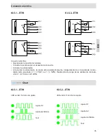
Electrical connection:
• Disconnect the system from all power.
• Connect the probe according to the connection diagram.
• Switch power on.
• The sensor automatically detects during power-up for each switching output individually, if the switching
output is connected to a „-“ (= PNP) or „+“ (= NPN) load.
Load resistors of the switching outputs (A1, A2) ≤ 20 kOhm.
KFI-5-1...ETW
KFI-5-2...ETW
LED green / Output adjustment
Adjustment S1
Adjustment S2
Factory set
Test
LED green / Output adjustment
Adjustment S1
Factory set
Test
KFI-5-1...ETW
KFI-5-2...ETW
chart:
A1
A1


