x
x
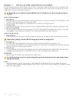
grip length
min 1.75 in
grip length
min 1.75 in
grip depth min 0.2 in
grip depth 0.2 in
fig. 3: Clamp specifications
walls exposed to load
min 0.156 in
REC Peak Energy Series Installation Manual - UL 1703
Ref: NE-06-03-M
Rev M - 03.2014
6
MouNTiNg THe PaNels
reC Peak energy panels are designed for capturing solar radiation and are not suitable for installation as overhead or vertical glazing. The panels
are considered to be in compliance with ul 1703, only when the panel is mounted specified by the mounting instructions below. The reC junction
box on the back of the panel is protected to iP67 and hence panels can be mounted in any orientation.
panel InstallatIon
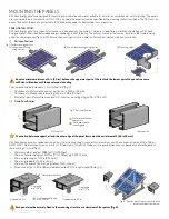
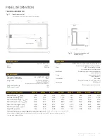
reC Peak energy panels are typically installed on a rail-based mounting system. There are three different methods of installing an reC Peak
energy panel, each decribed below, depending on the design load of the array. The rails can run under the frame or parallel to the frame, directly
under the clamping zones (fig 1a & 1b). ensure the mounting structure is able to withstand anticipated wind and snow loads.
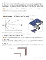
i) Rail specifications
walls for mechanical
connectors
walls exposed to
buckling load
fig. 2: rail specification
C channel rail
H channel rail
The clamps should be fastened to C or H channel rails (fig. 2).
•
Thickness of walls for mechanical connections: min. 0.156 in (4.0 mm)
•
Thickness of walls exposed to buckling load: min. 0.08 in (2.0 mm)
•
Moment of inertia for profile area about x-x: min array mounting diagram 0.4 in
4
(19.2 cm
4
)
ii) Clamp specification
fig. 1: Panel mounting options
The overlap between support rail and the outer edge of the panel frame must be a minimum of 1/64 in (6 mm).
reC Peak energy panels have been evaluated by ul for mounting using C-channel-rails in combination with end and mid clamps, 5/16 in (8 mm)
asTM f593C stainless steel screw and rail nuts. alternatively clamps with the below ratings and dimensions can be used to secure the panel to
the mounting structure (fig. 3):
•
Minimum yield strength of 2089 ton/ft² (200 Mpa)
•
Minimum tensile strength of 2610 ton/ft² (250 Mpa), e.g. 6005 T5 alloy.
•
Minimum grip length of 1.75 in (44.45 mm)
•
Minimum grip depth of 0.29 in (5 mm)
•
Minimum thickness of load carrying walls of 0.156 in (4 mm)
•
screw connection – 5/16 in (8 mm) stainless steel bolt, 5/16 in split washer (8 mm), nut
fig. 4: an array mounting system with each
panel secured at four points.
Each panel must be securely fixed to the mounting structure at a minimum of four points (fig.4).
(b) short side mounting using clamps
(c) Mounting holes
(a) long side mounting
using clamps
Ensure a minimum distance of 4 in (10 cm) between the uppermost part of the roof and the lowest part of the panel to ensure
sufficient airflow beneath the panels and aid cooling.

