background image

:> 

T

ests 

of front  detection 

• 

Tum  the  vehicle  key  to 

•oN• 

position,  don't  start  the  vehicle 

engine. 

• 

Brake the vehicle, move forward and backward either of the 2 

obstacle  simulators  15�75cm In front  of  vehicle,  system  should 

beep  and  visually  show  the  waming  zones,  distance  to  and 

direction  of  the  simulator. 

• 

Check  the  sensors  one  by  one 

:> 

T

ests 

of rear  detection 

• 

Tum  the  vehicle  key  to 

•oN• 

position,  don't  start  the  vehicle 

engine. 

• 

Go  into  reverse  gear,  move  forward  and  backward  the  2 

obstacle  simulators  20�200cm  behind  vehicle,  system  should 

beep  and/or  visually  show  the  wamlng  zones,  distance  to  and 

direction  of  the simulator. 

• 

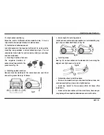
Check  the  sensors  one  by  one.  Refer  to  Fig.  37. 

PVCTUbeol 

•75mmX1M 

Fig.37 

Parking Sensor System 

•  DISCLAIMER 

� 

The  system  Is  designed  and  Intended  as  a  warning  aid  for 

vehicle  reverse  and  parking,  and  it  should 

be 

used  as  such. 

� 

Our  company  shall  accept  no  responsibility  for  any  accidents 

and/or  damage  caused  during  the  usage  of this  system. 

� 

The  detection  results  may  be  affected  when  system  works 

under very bad weather conditions (e.g.  strong wind, heavy rain, 

snow,  very  low  or  high  temperature)  or  on  complicated  roads 

(such  as  rugged  roads  or  roads  with  slope). 

� 

Ultrasonic and electromagnetic wave from other sources near 

the  system,  If any,  may  affect the  detection  results. 

II/22 

Содержание RVS-115

Страница 1: ......

Страница 2: ......

Страница 3: ...or system is a safety aid that is an integration of functional plezo ceramlc ultrasonic electronic computer data processing and other technologies Incorporating the principle of ultrasonic distance measurement and the technology of fuzzy processing of computer data It correctly detects obstacles behind and or in front ofthe vehicle and warns the driver with clear audio and or visual signals thus p...

Страница 4: ...em With 2 4 sensors this type only has a rear detection function Model number 111e model number Is marked on the girt box Dl ll m 1 TECHNICAL DATA OF REVERSE AID SYSTEM NO liEM PRODUCTSERIES REMARKS BUZZER l 0 LCD TFT 1 Worl ing Voltage VOC 10 5 28 Rated Volboge 12 10 5 16 1 Dlsplay dl b lnce 2 Rated Current max lOOmA 200mA 150mA 800mA It Is the detected dlstence rrom sensor to 3 Display DlslllnO ...

Страница 5: ...0 30 70 9 Storage Temperature C 35 80 35 80 e PRODUCT COMPOSinON The system mainly consists of the 3 units as follows Elactronlc Control Unit ECU It includes a micro computer control system and a signal processing circuit Parking Aid System has an ECU for front detection and another for rear detection JIJ3 REMARKS 1 Refer to the remartcs in Diagram 1 for tile details of test conditions 2 The accur...

Страница 6: ...obstacles in different ways sound and or display of warning zones distance to and direction of obstacles etc Refer to Dlagram 3 Dlagram 3 WARNING 1YPE OF WARNING UNIT MODE BUZZER LED LCD TFT Sound It It It It Distance It It It Zone It It Direction It Ii Ii Video It Parking Sensor System Fig 1 and Fig 2 show respectlvelythe composltlon ofPar1dng Ald System and Reverse Aid System Warning Unit Rg 1 C...

Страница 7: ...sors work for 10s and report the obstacles only if they are located in the display distance Reverse Aid System When reverse Is engaged system ls automatically activated and beep once before diagnostics and detection Diagnostics How It works When powered on the system detects its sensors first If some sensor Is working abnormally the warning unit will tell you its serial number Serial numbers of se...

Страница 8: ... problem ofsensorNo 3 otherwise you have l D lilce the same situation next time when you start the system EX 2 In case both sensors No 4 and 6 are abnormal When powered on system beeps onoe for0 5second then rapidly beeps4 times you should power off the sy stem and solve the problem of sensor No 4 When you re start the system after the beep of0 5 second system rapidly beeps 6 times Visual warning ...

Страница 9: ... 2SM D S0 4M Caution Zone 0 2SM DSO SOM 0 4M DS1 0M Safety Zone O SOM D S0 7SM 1 0M D S2 0M Remark ow is the distanee from obstacle to sensor U 7 Fig 5 Warning Zane When an obstacle appears In different warning zones system warns you accordingly In different modes as shown In Flg S Audible Warning System beeps when an obstacle appears In the Warning zones Diagram AUDIBLE WARNING MODE FOR REAR DETE...

Страница 10: ...X while an obstacle Is detected In rear Caution Zone meantime another obstlJc e Is found In front Dangerzone system onlyaudibly wams you ofthe obstacle located in tront DangerZone Indication of Distance and Zones Parking Sensor System Diagrillm 81 INDICATION OF DISTANCE AND ZONE FOR REAR DETECTION WARNING DISTANCE D DISTANCE ZONE ZONE M INDICATION MARK Blind Zone D 0 22 P m Danger Zone 0 22 SD S0 ...

Страница 11: ...audibly wams you ofthe obstacle located In front DangerZone Warning Unit Parking Aid System This system warns you with an LCD display that visually shows the warning zones distance to and direction of the obstacle II 9 Moreover the LCD with a built in buzzer has audible alarm function Warning Modes Please refer ID Flg 6 Instruction to Warning Mode Reverse and forward Slgnals They tell you system I...

Страница 12: ...er to Diagram 6 for audible warning mode About the buzzer The warning volume is adjustable with a switch on the lateral of buzzer See Flg 7 d Volume5wi1ch l l ow l HoHigh b Fig 7 About the Buzzer Parking Sensor System Warning mode of LED series This series warns you with a tricolor or blcolor double wave band and digital LED display plus a built In buzzer enabling you to know the warning zone dire...

Страница 13: ... ls reversing Direction signal It tells you by gleaming the relative sensor is detecting an obstacle thus visually shows the exact direction of the nearest obstacle If there are more than one obstacles Zone indication It tells you whether the obstacle is found in Safety Caution or Danger Zone Refer to Diagram 7 and Diagram 8 01 Flg 10 l CD Dlaplayfor RllVllrae Aid Syslem Sound alarm Refer to Diagr...

Страница 14: ...tuation behind vehicle and turns off automatically after reverse F eatures of rearvlew ml1TOr Using optical glass with specially plated layerfor antl glare function the mirrorserves as an excellent inside rearview mirror Direction signal It tells you by gleaming that the relative sensor Is detectlng an obstacle thus vlsually shows the exact direction of the nearest obstacle when there are more tha...

Страница 15: ...cle may not be detected i Lowobstacle st anding before atallone As shown In Fig 14 although Flg 14 Obstacle T is lower ltlan the sensors PartT wlll be C detected and warned first lZ113 Tc a I Ta lb because the rellectlon received by ltle sensorsfrom this partIs the strongest But when Obstacle T comes closer to vehicle and its reflection becomes stronger than that of ObstacleT the system starts to ...

Страница 16: ...Q After installation tests are necessary before use HOW TO INSTALL Installation Tools The tools listed in Fig 19 are required for installation Quick On i 11 A Cable Clip Parking Sensor System Pencil Fig 19 List of Installing Tools Note The 4 tools in the above rectangular pane are a triangle file a flat and a Philip head screwdrivers and a pair of pliers Where to Install Fig 20 a nd Fig 21 are the...

Страница 17: ... tenslble clips to the original Inside rearvlew mirror Detecting unit Install sensors in rear or front bumpers m1s Installation Procedure l General layout Determine where to Install ECU and warning unit according to your vehicle installation drawings or your experience Make sure the power cable of ECU should be easily connected l Sensor Installation For details refer ro Tips on Sensor Inst a lat o...

Страница 18: ... i l aa m Display Unit L _LED LC _J Fig 22 Connection between each unit of Reverse Aid System Parking Sensor System GND ACC12V GND DC12V Power of Brake Light _ 1 a 1511 a Display Unit lt 1i il 1 2BM Fig 23 Connection between each unit of Parking Aid System lZ116 ...

Страница 19: ...fer to Powering up on PElf 6 20 i Installation of each unit For details refer to where ta insta J on page14 Test For details refer to Alter Jnst allatJon Tests on page 2l Tips on Sensor lnstallatlon i Types of sensor There are 2 types of sensor adhesive and recess ones see Fig 25 Adhesive type Flg 25 To be stuck on the bumper surface Usually our system can be equipped with 2 sensors of such type w...

Страница 20: ... Fi 29 v v x Sensors must be installed at the same level and over SOcm above the ground See Fig 27 below Parking Sensor System About angle for installing sensors Install sensors somewhere appropr1ate to avoid detecting any part of your vehicle itself Refer to Fig 28 Fig 28 InstalIing steps See Fig 29 sensor cables can be leaded into trunk along the edge of rear Ilght cover or trunk lid Detenmlne w...

Страница 21: ... and vertical positioning See Ag 32 and 33 Lw Is the width of vehlcle The horlzontal distance between sensors Is decided by the width of vehlcle It Is recommended to install the side sensors slightly closer to the lateral sides of vehicle for wider detection angle when needed n719 1 4L 1 4 L 214 L 0 3 0 4m L Installing steps Marie with a pencil the installing positions for sensors on bumper Make h...

Страница 22: ... L ii 11 E M GND L llc iNl i _ _ 12VDC ROY9189 U t Power connection of parking aid system Power connection of rear ECU The rear ECU gets power from the reverse light of vehicle as shown in Fig 34 Power connection of front ECU Parking Sensor System Front ECU has 2 power cables one is connected to ACC for power the other Is connected to the brake Ilght cable for the signal that activates the system ...

Страница 23: ...f sensors are installed In steel bumpers Ultrasonic and electromagnetic wave from other sources near the system if any may affect the detection results e AFTER INSTAUATION TESTS m21 Test Subjects Audible warning Refr r to Dlagl llms 5and 6 Distance direction and warning zones Refr r to Diagrams 7 and 8 Startup of reverse aid system Once reverse is engaged system is automatically activated when rev...

Страница 24: ... visually show the wamlng zones distance to and direction of the simulator Check the sensors one by one Refer to Fig 37 PVCTUbeol 75mmX1M Fig 37 Parking Sensor System DISCLAIMER The system Is designed and Intended as a warning aid for vehicle reverse and parking and it should be used as such Our company shall accept no responsibility for any accidents and or damage caused during the usage of this ...

Страница 25: ...ion of sensors 1 Follow the UP mark and re install sensors same while distance to obstacle 2 Adjust the position of detecting angle to avoid downward var1es 2 Wrong Installing angle of sensors detection In case no obstade Is found In the 1 Some sensor Is not tightly fixed detection range display always 1 Check if the sensor is well fixed in bumper shows p ar sroP and 2 System is detecting vehicle ...

Отзывы: