background image


User’s Manual

GSM35

23

RTD Finland Oy

Chapter 5  


B

OARD OPERATION AND PROGRAMMING

This chapter shows you how to program and use your GSM35. It provides
a general description of the I/O map. Detailed serial port programming tips
are not within the scope of this manual.

Defining the Memory Map

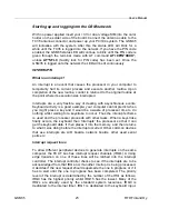
The memory map of the GSM35 occupies two groups of eight bytes of
host PC I/O space. This window is freely selectable by the user as
described in 

Chapter 2, Table 2-2. 

After setting the base address you

have access to the internal resources of the GSM35 control logic. These
resources are not described in detail, since they are mapped as a
standard PC serial port. For more details on the EXAR ST16C550IJ44
UART chip programming please download the component specific data t
from the website: http://www.exar.com/products/st16c550.html

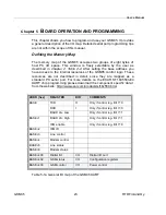
ADDR (hex)

REGISTER

DIR

COMMENTS

TXD

O

Only if control reg. Bit 7=0

RXD

I

Only if control reg. Bit 7=0

BASE

BAUD div. Low

Only if control reg. Bit 7=1

BAUD div. High

Only if control reg. Bit 7=1

BASE+1

IRQ enable

Only if control reg. Bit 7=0

BASE+2

IRQ ID

BASE+3

Line control

BASE+4

Modem control

BASE+5

Line status

BASE+6

Modem status

BASE+400

Digital I/O

I/O

Digital I/O port

BASE+402

GSM status

I/O

Configuration registers

BASE+403

GSM control

I/O

Power control

Table 5-1a General I/O map of the GSM35 UART

Содержание GSM35

Страница 1: ...GSM35 900 1800MHz GSM Modem Module User s Manual Hardware revision 1 1 I IS SO O9 90 00 01 1 a an nd d A AS S9 91 10 00 0 C Ce er rt ti if fi ie ed d ...

Страница 2: ...GSM Modem Module User s Manual REAL TIME DEVICES FINLAND OY LEPOLANTIE 14 FIN 00660 HELSINKI FINLAND Phone 358 9 346 4538 FAX 358 9 346 4539 EMail sales rtdfinland fi techsupport rtdfinland fi Websites http www rtdfinland fi http www rtdusa com ...

Страница 3: ...mply with this prohibition may lead to temporary suspension or permanent cancellation of cellular services for the person who infringes this prohibition and or legal action against said person 2 ENVIRONMENTS WITH EXPLOSIVE SUBSTANCES Users are not advised to use the GSM35 in automotive service stations Users are reminded of the necessity to comply with restrictions regarding the use of radio devic...

Страница 4: ...he publication date Information in this manual may change without prior notice from RTD Finland Oy Published by Real Time Devices Finland Oy Lepolantie 14 FIN 00660 Helsinki Finland Copyright 2002 Real Time Devices Finland Oy All rights reserved Printed in Finland PC XT PC AT are registered trademarks of IBM Corporation PC 104 is a registered trademark of the PC 104 Consortium The Real Time Device...

Страница 5: ...mes with your board 9 Using this manual 9 When you need help 9 Chapter 2 Board settings 10 Factory configured jumper settings 11 Base address jumpers 12 Host interrupts 14 Chapter 3 Board installation 15 Board installation 15 General purpose digital I O connector 16 SIM card holder 17 Chapter 4 Hardware description 19 The GSM wireless modem module 20 GSM antenna considerations 20 SIM card reader 2...

Страница 6: ...s illustrating address 2E8h Fig 2 3 Interrupt jumpers from left to right IRQ 2 5 6 7 10 11 12 15 and G Fig 3 1 GSM35 integrated in a RTD PC 104 cpuModule stack together with a HPWR104HR and a CMM series cpuModule Fig 3 2 Digital I O connector layout of the GSM35 Fig 3 3 External SIM card interface of the GSM35 Fig 3 4 ESIM2035 External SIM card interface board Fig 3 5 External SIM card header J25 ...

Страница 7: ...ragraphs briefly describe the major features of the GSM35 A more detailed discussion is included in Chapter 4 Hardware description The boards installation is described in Chapter 2 Board Installation GSM cellular modem The Real Time Devices GSM35 wireless GSM modem unit provides a direct and reliable GSM connection to stationary or GSM 900 1800 mobile fields around the world GSM connectivity is ac...

Страница 8: ...herefore no special communication drivers are needed to receive data from your GSM35 board The address and interrupt of your serial channels can be individually set with the onboard jumper fields I O interfaces The GSM35 can be controlled and monitored from the software through two dedicated I O registers A special I O connector is available for the user to connect to the general purpose TTL level...

Страница 9: ...ter kit is SK GSM35 Using this manual This manual is intended to help you install your new GSM35 module and get it working quickly while also providing enough detail about the board and it s functions so that you can enjoy maximum use of it s features even in the most demanding applications When you need help This manual and all the example programs will provide you with enough information to full...

Страница 10: ... jumper settings which can be changed to suit your application and host computer configuration The factory settings are listed and shown in the diagram at the beginning of this chapter Make sure you completely study and understand this chapter before making changes to these settings ...

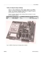
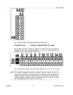
Страница 11: ...of the jumpers The following paragraphs explain how to change the factory jumper settings to suit your specific application Table 2 1 Factory configured jumper settings Please see figure 2 1 below for more detailed locations JUMPER NAME DESCRIPTION NUMBER OF JUMPERS FACTORY SETTING BASE Base Addresses 6 2E8 6E8 IRQ Host interrupts 11 1 5 G jumper closed Fig 2 1 GSM35 1 Board layout showing jumper ...

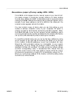
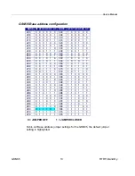
Страница 12: ...e it s own reserved memory addresses which are being already used by another peripheral device erratic performance can occur and the data read from the board may be corrupted To avoid this problem make sure you set up the base address by using the six jumpers on the right side of the board this allows you to choose from a number of different addresses in your host computer s I O map Should the fac...

Страница 13: ...0 268 0 0 1 1 0 1 368 1 0 1 1 0 1 270 0 0 1 1 1 0 370 1 0 1 1 1 0 278 0 0 1 1 1 1 378 1 0 1 1 1 1 280 0 1 0 0 0 0 380 1 1 0 0 0 0 288 0 1 0 0 0 1 388 1 1 0 0 0 1 290 0 1 0 0 1 0 390 1 1 0 0 1 0 298 0 1 0 0 1 1 398 1 1 0 0 1 1 2A0 0 1 0 1 0 0 3A0 1 1 0 1 0 0 2A8 0 1 0 1 0 1 3A8 1 1 0 1 0 1 2B0 0 1 0 1 1 0 3B0 1 1 0 1 1 0 2B8 0 1 0 1 1 1 3B8 1 1 0 1 1 1 2C0 0 1 1 0 0 0 3C0 1 1 1 0 0 0 2C8 0 1 1 0 0 ...

Страница 14: ...errupt channels available on the host computer XT AT bus Fig 2 3 Interrupt jumpers from left to right IRQ2 5 6 7 10 11 12 14 15 and G Note The GSM35 hardware supports interrupt sharing Jumper G must be closed on one module per used interrupt For example if two boards share interrupt number 7 only one board may have the G jumper closed The G jumper connects a 1KOhm resistor to ground while the shar...

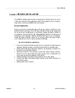
Страница 15: ...Before installing the board in your computer check the power cabling Failure to do so may cause the power supply unit to malfunction or even cause permanent damage General installation guidelines Touch the grounded metal housing of your computer to discharge any antistatic buildup and then remove the board from its antistatic bag Hold the board by the edges and install it in an enclosure or place ...

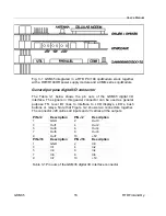
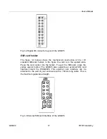
Страница 16: ... connector can be used as general purpose TTL level I O lines to interface to LCD displays LED s bush buttons or relays Note that Figure 3 2 shows two connectors together The connector J28 carries all inputs and J3 carries all the outputs PIN J2 Description PIN J2 Description 1 GND 2 Out0 3 Out1 4 Out2 5 Out3 6 Out4 7 Out5 8 Out6 9 Out7 10 5V PIN J16 Description PIN J16 Description 1 GND 2 In0 3 I...

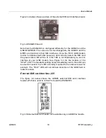
Страница 17: ... the figure the card is in the ejected state Press the card carrier into the holder To eject the SIM card press the yellow ejector button The GSM35 also supports an external SIM card interface board the ESIM2035 This external card interface can be attached to the wall of your enclosure with a 150mm long cable This is the maximum guaranteed length Fig 3 3 External SIM card interface of the GSM35 ...

Страница 18: ... the SIM card the green status LED will be lit If the LED is not illuminated you can not interface to your GSM modem See Figure 3 3 for the location of the STAT LED The header mounting holes immediately next to the LED can be used to connect to an LED externally mounted to the enclosure wall for example The STAT LED will not indicate detection of the GSM field or network access External SIM card i...

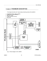
Страница 19: ...ter 4 HARDWARE DESCRIPTION This chapter describes the major hardware building blocks of the GSM35 The GSM wireless modem module GSM antenna considerations SIM card reader UART serial port circuitry Digital I O Fig 4 1 Block diagram of the GSM35 ...

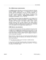
Страница 20: ...X connector The mating antenna connectors and cables are supplied from RTD Finland Oy Temperature monitoring is possible using the onboard temperature sensor Limit data can be interrogated from the GSM35 status register bits 2 3 GSM Antenna considerations The antenna used must meet the following specifications Frequency 890 910 MHz TX 935 960MHz RX Impedance 50 Ohms VSWR 1 7 1 TX 1 9 1 RX Gain 1 5...

Страница 21: ...GSM35 is logged into the network If the reply for example is CREG 0 1 it means that connection to the home network is valid A complete AT instruction set documentation is included in the TC35 user s manual UART serial port circuitry GSM data is sent and received through a standard 16C550 compatible UART All today s operating systems will recognize and support this serial communication device The G...

Страница 22: ...rovided This port includes 8 TTL level digital outputs that are cleared to 0 after system reset Also are included 8 digital inputs with 10K Ohm pull down resistors These I O s are located on the left side of the board These I O s are ideal to be used to interface to LCD displays LED s pushbuttons or other low power controls ...

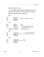
Страница 23: ...e resources are not described in detail since they are mapped as a standard PC serial port For more details on the EXAR ST16C550IJ44 UART chip programming please download the component specific data t from the website http www exar com products st16c550 html ADDR hex REGISTER DIR COMMENTS TXD O Only if control reg Bit 7 0 RXD I Only if control reg Bit 7 0 BASE BAUD div Low Only if control reg Bit ...

Страница 24: ...r reset Write Bit 0 RESERVED Bit 1 EN_INT 0 UART interrupt enabled 1 disabled Bit 2 RESERVED Bit 3 RESERVED Read Bit 0 EN_RST state Bit 1 EN_INT state Bit 2 TEMP_LOW 1 Board temperature below 20C Bit 3 TEMP_HIGH 1 Board temperature over 70C BASE 403 GSM Control R W 0x00 after reset Write Bit 0 Ignition signal 1 0 results in IGN signal Bit 1 Powerdown of the TC35 1 Power down 0 Power on Bit 2 RESER...

Страница 25: ...edict when you might press a key and it would be a waste of processor time to do nothing whilst waiting for a keystroke to occur Thus the interrupt scheme is used and the processor proceeds with other tasks When a keystroke finally occurs the keyboard then interrupts the processor so that it can get the keyboard data It then places it into the memory and then returns to what it was doing before th...

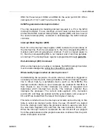
Страница 26: ...roller must be acknowledged by writing the value 20h to port 20h What exactly happens when an interrupt occurs Understanding the sequence of events when an interrupt is triggered is necessary to correctly write interrupt handlers When an interrupt request line is driven high by a peripheral device such as the GSM35 the interrupt controller checks to see if interrupts are enabled for that IRQ It th...

Страница 27: ...em stack These were pushed onto the stack when entering the ISR Most compilers allow you to identify a function as an interrupt type and will automatically add these instructions to your ISR with one exception most compilers do not automatically add the EOI command to the function you must do it yourself Other than this and a few exceptions discussed below you can write your ISR as any code routin...

Страница 28: ...nd the scope of this manual The second major concern when writing ISR s is to make them as short as possible in term of execution time Spending long times in interrupt service routines may mean that other important interrupts are not serviced Also if you spend too long in your ISR it may be called again before you have exited This will lead to your computer hanging up and will require a reboot You...

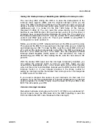
Страница 29: ...e current IMR at I O port 21h and set the bit that corresponds to the IRQ The IMR is arranged so that bit 0 is for IRQ0 and bit 7 is for IRQ7 See the paragraph entitled Interrupt Mask Register IMR earlier in this discussion for help in determining your IRQ s bit After setting the bit write the new value to I O port 21h With the startup IMR saved and the interrupts temporarily disabled you can assi...

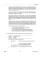
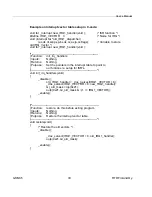
Страница 30: ... Inputs Nothing Returns Nothing Purpose Set the pointers in the interrupt table to point to our funtions ie setup for ISR s void init_irq_handlers void _disable old_IRQ1_handler _dos_getvect IRQ1_VECTOR 8 _dos_setvect IRQ1_VECTOR 8 new_IRQ1_handler Gi_old_mask inp 0x21 outp 0x21 Gi_old_mask 1 IRQ1_VECTOR _enable Function restore do this before exiting program Inputs Nothing Returns Nothing Purpose...

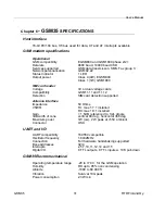
Страница 31: ...12 Detection SIM card detection supported Antenna Interface Impedance 50 Ohms VSWR TX max 1 7 1 installed RX max 1 9 1 installed Gain 1 5dB referenced to 1 2L dipole 3dB width of cone vertical 80 deg horizontal 360 deg Maximum power 1W cw 2 W peak at 55C ambient Connector OSX UART and I O UART compatibility 16C550 compatible Oscillator frequency 1 8432MHz Connection Full hardware handshaking suppo...

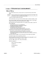
Страница 32: ...hat other devices were connected to the product How was power supplied to the product What features did and did not work What was being done when the product failed What were environmental conditions when the product failed 5 Indicate the method we should use to ship the product back to you We will return warranty repairs by UPS Ground at our expense Warranty repairs may be returned by a faster se...

Страница 33: ...of REAL TIME DEVICES OR AS A RESULT OF SERVICE OR MODIFICATION BY ANYONE OTHER THAN REAL TIME DEVICES EXCEPT AS EXPRESSLY SET FORTH ABOVE NO OTHER WARRANTIES ARE EXPRESSED OR IMPLIED INCLUDING BUT NOT LIMITED TO ANY IMPLIED WARRANTIES OF MERCHANTABILITY AND FITNESS FOR A PARTICULAR PURPOSE AND REAL TIME DEVICES EXPRESSLY DISCLAIMS ALL WARRANTIES NOT STATED HEREIN ALL IMPLIED WARRANTIES INCLUDING I...

Отзывы: