

User’s Manual
GSM35
17
RTD Finland Oy
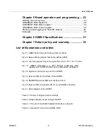
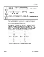
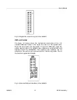
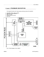
Fig 3-2 Digital I/O connector layout of the GSM35
SIM card holder
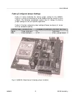
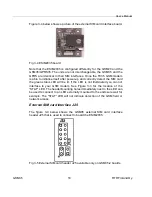
The figure 3-3 below shows the mechanical construction of the +3V
standard SIM-card holder. In the figure the card is in the ejected state.
Press the card carrier into the holder. To eject the SIM-card, press the
yellow ejector button. The GSM35 also supports an external SIM card
interface board the ESIM2035. This external card interface can be
attached to the wall of your enclosure with a 150mm long cable. This is
the maximum guaranteed length.
Fig 3-3 External SIM card interface of the GSM35.


