Gas Pressure
Check the burner from the test point. This is located on the burner supply pipework on
Natural Gas models and on the burner injector on L.P.G.models
See appliance data badge for pressure settings
Adjustment of the Burner Gas pressure
Adjust the pressure at the gas valve if required.
See valve picture
There are two adjustments, High and low setting. These are located at the front of the
valve at the head of the blue solenoid.
High adjustment – This is the outer Brass hexagonal nut
Low Adjustment – This is the inner Red adjustment screw
When adjusting the high setting hold the low adjuster in place otherwise both may
turn.
Front fascia panel
Fit front fascia panel onto the fixing screws.
Side reflectors
Fit side reflectors by tilting on an angle locating base onto fascia panels and placing
vertical. A retaining clip is already fixed to the firebox to secure reflector in place.
Check the fire is operating correctly and test for spillage of combustion products.
Fitting Trims to Firebox
Fit the trims to the firebox. The trim brackets are designed to hang over the flange on
each side of the firebox. Each flange has provision to be moved slightly in or out to
allow the bracket to fit. The flanges have a raised square near the base of the fire. The
Velcro pad is fixed to this by removing the backing from one side of the pad and
pushing firmly in place. Then remove backing from the other side. Repeat on opposite
side. Hang trim on brackets and check for level then firmly push onto Velcro pads.
Optional four sided Trims
Four sided trims are available as an optional extra with the through wall fire.
This is for use when one or both sides of the fire has a hearth lower than the base of
the fire. The method of fixing is the same as the standard trim.
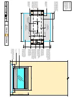
Optional glass panel for inside outside installations.
The through wall fire can be installed through an outside wall with the glass side of
the fire on the outside. In these situations a second glass panel must be ordered and
fitted over the existing glass panel at the time of installation.
Please note Real Fires do not supply any weatherproof flashings for the Through
wall fire.
Once the installation is complete, instruct the user on the operation of the fire
and complete commissioning details in Real Fires user manual.
All installations must be certified


