background image

Installing the Optional Sensors 

Your React radio system has several optional sensors that you can install in your vehicle and connect to 
the transceiver. When properly installed and connected, these sensors will send information back to the 
React so that you can monitor the readings while you drive. 

Receiver Battery Sensor 

The transceiver monitors the receiver battery voltage from the POWER receptacle. There is no 
installation necessary for this sensor. 

Voltage Sensor 

The voltage sensor is used to monitor the voltage of a separate battery pack (for example, an electric 
car’s main battery pack). In a Nitro car, this sensor is not needed. 


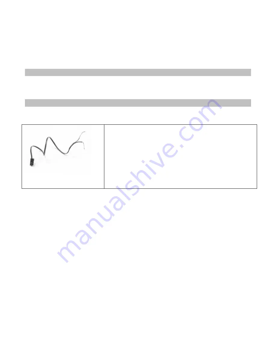
Connecting the Voltage Sensor 
 
1. Connect the RED wire of the voltage sensor to the positive 
terminal and the BLACK wire of the voltage sense to the negative 
terminal of the battery pack you want to monitor. 

2. Carefully route, protect, and secure the sensor wires. 

3. Plug the voltage sensor into the BATT receptacle. If your voltage 
sensor only has two wires, connect the RED wire to the center pin 
and the black wire to either outside pin. 


Содержание nomadio

Страница 1: ...Link to Download Desktop Software HTTP SUPPORT NOMADIO NET REACT User s Guide...

Страница 2: ......

Страница 3: ...uttons 9 Grip Buttons 9 Charging and Installing Batteries 10 Installing the Batteries 10 Charging the Batteries 11 Installing the Transceiver 12 Mounting the Transceiver 12 Connecting the Transceiver...

Страница 4: ...point as follows 29 Trim and EPA Interaction 29 Steering Right End Point 30 Trim and EPA Interaction 31 Steering Servo Reverse 32 Changing the Steering Servo Reverse Setting 32 Steering Servo Type 32...

Страница 5: ...Dual Rate and End Point Adjustment 53 Low End Point 53 Adjusting the Low End Point 54 High End Point 55 Adjusting the High End Point 56 Channel 3 4 Dual Rate Mode 57 Changing the Channel 3 4 Dual Rat...

Страница 6: ...gital RC Desktop 83 Minimum System Requirements 83 Installing the RC Desktop 84 Connecting the React to your Computer 87 2 Plug the smaller end of the included USB cable into the cable with the matchi...

Страница 7: ...Nomadio 1 Year Limited Warranty 99 Warranty Coverage 99 Exclusions and Limitations 99 Consumer Protection Laws 101 Obtaining Warranty Service 101...

Страница 8: ...and your servo information Menu Screen This screen is the gateway to the React s menu system which is described in detail later You can always go back to the driving screen by just pressing the menu...

Страница 9: ...any changes made and resets value to where it was before editing started Resets the value to its factory default Trim Buttons Button In the drive screen T1 Adjusts the steering trim T2 Adjusts the st...

Страница 10: ...the software on the receiver The RC Desktop will instruct you when a software upgrade is available Installing the Batteries 1 Plug the battery connector into the receptacle in the battery compartment...

Страница 11: ...will sense a low battery and will begin charging automatically To manually begin charging a battery hit the key The LCD status will display Charging and the timer at the bottom of the screen will begi...

Страница 12: ...ansceiver so the sensors can be easily connected to it Antenna The thinner portion at the end of the antenna wire must be outside the vehicle body DO NOT CUT the antenna wire Connecting the Transceive...

Страница 13: ...Power Steering servo Steering Throttle servo or ESC Throttle Shifting servo Shft CH3 FCC Compliance Reminder If you install the React transceiver inside of a vehicle and you are not the final end use...

Страница 14: ...ary for this sensor Voltage Sensor The voltage sensor is used to monitor the voltage of a separate battery pack for example an electric car s main battery pack In a Nitro car this sensor is not needed...

Страница 15: ...ensor in place by wrapping them around a cylinder head or ESC heat sink Alternately a high temperature epoxy may be used to secure the sensor When installing on a nitro motor place the sensor as low a...

Страница 16: ...gnets on your motor for magnetic reasons electric motors and balance reasons nitro motors Smaller diameter mounting points are better The tach sensor must be able to be mounted within 1 2mm of the mag...

Страница 17: ...it into the DIGITAL receptacle Plug connector into transceiver tachometer connector pin 1 designated with a red wire and an arrow on the connector body housing corresponds with the keyed end of trans...

Страница 18: ...under the barcode on the FCC label is displayed and you are given the option of connecting to that transceiver or looking for another Now every time you turn on the React and set it to the appropriat...

Страница 19: ...u Menu Go to the selected sub menu Menu Move to the next higher menu item Menu Move to the next lower menu item Menu Go to the selected sub menu Drive Display next statistic Menu Decrease the selected...

Страница 20: ...ows the function menu structure for the top level menu All main sub menus may be accessed from the top menu level Channels 3 4 have identical setups and are documented together Manage Models Active Mo...

Страница 21: ...initially adjusted steering sub trim S teering Ch1 T hrottle Ch2 S hift Ch3 Ch4 S teering T rim On the driving screen steering trim is represented by the position of the pointer on the upper bar As yo...

Страница 22: ...n 3 Navigate to Trim or Value Description 0 Steering trim is centered within the servo range ve value 100 1 Steering trim is to the LEFT 4 Change the value or ve value 1 100 Steering trim is to the RI...

Страница 23: ...ercentage of servo range configured by end point adjustments S teering Ch1 T hrottle Ch2 S hift Ch3 Ch4 Dual Rate Range On the driving screen steering dual rate range is represented by the solid lengt...

Страница 24: ...full range For example value 50 gives 50 of full servo range 4 Change the value or 100 Steering servo range is set to full 100 Adjusting Steering Dual Rate using the Trim Buttons You can also use the...

Страница 25: ...ntial milder response Steering wheel turned full RIGHT Servo travel LEFT A negative ve exponential value gives a milder steering response near the steering neutral point making it LESS responsive to s...

Страница 26: ...ccess the top function menu from the driving screen 2 Navigate to the Steering Ch1 menu or then 3 Navigate to Expo or Value Description 0 Neutral steering response linear ve value 1 to 100 Milder stee...

Страница 27: ...ng range If you find that you have to use a large amount of steering sub trim to get the vehicle to drive straight you should consider resetting the steering sub trim to 0 and re adjusting the servo h...

Страница 28: ...cally able Adjust steering throw to change steering characteristics when turning to the left For example if the current amount of steering throw to the left causes oversteer or understeer when turning...

Страница 29: ...will overdrive most servos Use the navigation controls to adjust the left end point as follows 1 Access the top function menu from the driving screen 2 Navigate to the Steering Ch1 menu or then 3 Navi...

Страница 30: ...cur on full servo throw to the right For example if the servo is trying to turn the steering system to the right farther than it is mechanically able Adjust steering throw to change steering character...

Страница 31: ...g the left end point value An end point setting of 100 the default is typical for most servos and should always be used for ESCs Larger setting values will overdrive most servos Use the navigation con...

Страница 32: ...eering Servo Type Steering servo type lets you select the type of steering servo analog or digital in the vehicle Analog servos are sent signals at 50 frames sec while Digital servos are sent signals...

Страница 33: ...at is applied to motions back toward center that are above the trigger setting 100 is the maximum servo movement rate 1 is the minimum rate Default is 100 full speed Changing the Steering Speed Intera...

Страница 34: ...etting up the vehicle the throttle trim setting should be set to 0 On a throttle servo the servo horn should be positioned as appropriate on the servo T hrottle T rim On the driving screen throttle tr...

Страница 35: ...vigate to Trim or Value Description 0 Throttle trim is centered within servo range ve value 100 1 Throttle trim is to the BRAKE end 4 Change the value or ve value 1 100 Throttle trim is to the THROTTL...

Страница 36: ...is expressed as a percentage of servo range configured by end point adjustments T hrottle Dual Rate Range On the driving screen throttle dual rate range is represented by the solid length of the midd...

Страница 37: ...ust throttle dual rate Dual Rate and End Point Adjustment Full servo range is determined by the throttle and brake end point adjustments The dual rate value determines the relative servo range between...

Страница 38: ...tle inputs without changing overall throttle travel like Dual Rate would Neutral 1 100 quick 0 linear Servo travel THROTTLE ve exponential quicker response Full throttle A positive ve exponential valu...

Страница 39: ...braking inputs without changing overall throttle travel like Dual Rate would Neutral 1 100 quick 0 linear Servo travel BRAKE ve exponential quicker response Full brake A positive ve exponential value...

Страница 40: ...to use a large amount of throttle sub trim to adjust the throttle position you should consider resetting the steering sub trim to 0 and re adjusting the servo horn on the servo output shaft Adjusting...

Страница 41: ...used to do the following Limit throttle throw to reduce mechanical binding or servo strain that may occur on full servo throw to the brake end For example if the servo is trying to pull a mechanical...

Страница 42: ...ys be used for ESCs Larger setting values will overdrive most servos Adjusting the Brake End Point The brake end point value is a relative value and is expressed as the percentage of full travel to th...

Страница 43: ...to reduce mechanical binding or servo strain that may occur on full servo throw to the throttle end For example if the servo is trying to pull a mechanical throttle linkage farther than it is mechanic...

Страница 44: ...ult is typical for most servos and should always be used for ESCs Larger setting values will overdrive most servos Adjusting the Throttle End Point The throttle end point value is a relative value and...

Страница 45: ...function menu from the driving screen 2 Navigate to the Throttle Ch2 menu or then 3 Navigate to DR Mode or Value Description Both Dual rate affects travel in both direction Throttle Dual rate affects...

Страница 46: ...ging the Throttle Servo Reverse Setting Use the navigation controls to change the throttle servo reverse setting as follows 1 Access the top function menu from the driving screen 2 Navigate to the Thr...

Страница 47: ...better with the digital setting Some ESCs may not operate at all with the higher frame rate Try both settings and choose the best performance Changing the Throttle Servo Type Use the navigation contr...

Страница 48: ...ll speed Brake Speed determines the percentage of full speed that is applied to braking movements that are above the trigger setting 100 is maximum servo movement rate 1 is minimum rate Default is 100...

Страница 49: ...le range that will be limited Brake Trigger The percentage of full braking range that will be limited Interaction with other Settings Servo Speed is applied after Expo The trigger levels refer to the...

Страница 50: ...ing centered positions of the servos When initially setting up the vehicle the shift servo trim setting should be set to 0 On the servo the servo horn should be positioned as appropriate on the servo...

Страница 51: ...e to the Channel 3 or Channel 4 menu or then 3 Navigate to Trim or Value Description 0 Shift servo trim is centered within the servo range ve value 100 1 Shift servo trim is to the LOW end 4 Change th...

Страница 52: ...resents the servo range as set by the dual rate value Ch3 Ch4 Dual Rate Ranges Changing the dual rate setting has the following visual effect on the driving screen bars Full servo range is used Lower...

Страница 53: ...GH end On the driving screen the low end point is represented by the length of the bar to the left of the pointer on the lower bar The greater the left length of the bar the greater the low end point...

Страница 54: ...from the driving screen 2 Navigate to the Channel 3 or Channel 4 menu or then 3 Navigate to Low End Point or Value Description 0 Minimum low end point allows NO travel to low end 1 199 Low end point...

Страница 55: ...ttings The high end point is set independently of the low end point which adjusts how far the servo moves to the LOW turns end On the driving screen the high end point is represented by the length of...

Страница 56: ...cal for most servos and should always be used for ESCs Larger setting values will overdrive most servos Adjusting the High End Point The high end point value is a relative value and is expressed as th...

Страница 57: ...avigate to the Channel 3 or Channel 4 menu or then 3 Navigate to DR Mode or Value Description Both Dual rate affects travel in both direction Throttle Dual rate affects throttle travel only Useful to...

Страница 58: ...Channel 3 4 Servo Reverse Setting Use the navigation controls to change the servo reverse setting as follows 1 Access the top function menu from the driving screen 2 Navigate to the Channel 3 or Chann...

Страница 59: ...th the digital setting Some ESCs may not operate at all with the higher frame rate Try both settings and choose the best performance Changing the Channel 3 4 Servo Type Use the navigation controls to...

Страница 60: ...button again moves the shift servo back to Low Hold Servo starts at Low Holding the grip button moves the shift servo to High Releasing the grip button moves the servo back to Low 4 Change the value...

Страница 61: ...before the speed limiter becomes active At 0 limiting is always active input is always 0 At 50 limiting is only active if the throttle is on half way or more Brake Trigger sets the minimum amount of c...

Страница 62: ...full throttle range that will be limited Brake Trigger The percentage of full braking range that will be limited Interaction with other Settings Servo Speed is applied after Expo The trigger levels re...

Страница 63: ...at the React delivers to you based on Reacts and user actions Note that you configure the actual vibration patterns which are triggered by these events through the Digital RC Desktop software on your...

Страница 64: ...re 0 450 degrees 270 degrees Vibe Temp Vibe Over temperature warning One level for each temperature sensor port 4 total Speed 0 200 55 Vibe Temp Vibe Speed threshold notification Connection N A Vibe C...

Страница 65: ...itro engine by running it at high idle just shy of the clutch engaging Configuring Idle Up Use the navigation controls to configure Idle Up as follows 1 Access the top function menu from the driving s...

Страница 66: ...g screen 2 Navigate to the Advanced menu or then 2 Navigate to the Idle Up submenu or then Value Description Armed Enables or disables the AutoStart function 4 Change the values or Level The position...

Страница 67: ...shold above which ABS is triggered Delay The time in seconds 0 0 2 0 default 0 the brake must be above the trigger level before ABS engages Depth A percentage 1 100 default 50 indicating the reduction...

Страница 68: ...fe menu or then 4 Navigate to Steering or Value Description Hold Steering servo holds last known position 5 Change the steering servo failsafe setting or Set Steering servo goes to set failsafe positi...

Страница 69: ...n Before the countdown ends use the React controls to set the servo failsafe positions For example on a nitro car set steering to centered and throttle to full brake At the end of the countdown a conf...

Страница 70: ...allation point and the wheels If you are not sure of these ratios you should probably use the Measurement method Multiply tire diameter by PI 3 14159 to get length of one tire revolution Multiply that...

Страница 71: ...f it should work out to an even number of inches or CM that will be your rollout parameter If your measurement is to the closest 1 8th of an inch then in order to eliminate the fraction you must multi...

Страница 72: ...r ratio between the motor and your tach sensor Enter the ratio in whole numbers 1 1000 using these two settings Example 1 If 4 revolutions of your motor or clutch bell makes your magnets rotate once y...

Страница 73: ...s limited by Throttle Brake endpoints Activating Deactivating Tank Mode Use the navigation controls to select the active model as follows 1 Access the top function menu from the driving screen 2 Navig...

Страница 74: ...in the list When binding with a transceiver in a vehicle you must first select the active model to identify the vehicle When preparing to operate a vehicle select the active model then turn on the veh...

Страница 75: ...el 5 and make it the default model You can change the model name from your PC using the Digital RC Desktop Creating a New Model Use the navigation controls to create a new model as follows 1 Access th...

Страница 76: ...del as follows 1 Access the top function menu from the driving screen 2 Navigate to the Manage Models menu or then 3 Navigate to Active Model or 4 Navigate to the model you want to delete or 5 Navigat...

Страница 77: ...he top function menu from the driving screen 2 Navigate to the Manage Models menu or then 3 Navigate to Active Model or 4 Navigate to the model for which you want to copy the settings or 5 Navigate to...

Страница 78: ...odel Use the controls to rebind to a model as follows 1 Access the top function menu from the driving screen 2 Navigate to the Manage Models menu or then 3 Navigate to Active Model or 4 Navigate to th...

Страница 79: ...ate to Vibrator or 4 Turn the vibration option on off or Contrast You can set the contrast of the display screen to make it lighter or darker for better visibility at your preferred viewing angle Adju...

Страница 80: ...nor tach rollout to the new units You must go through and reset those settings manually after a conversion Selecting Unit System Use the navigation controls to adjust the display contrast level as fol...

Страница 81: ...Navigate to and activate Calibrate or then 4 At the confirmation screen 9 Select Yes to recalibrate 10 Select No to cancel the operation or 5 Confirm your selection 6 Perform the calibration routine b...

Страница 82: ...en and user name This is a great way to show off your customized graphics to your friends Viewing the React About Screen Use the navigation controls to view the about screen as follows 1 Access the to...

Страница 83: ...ormation to your computer make changes and then upload the newer settings Updating the React firmware is as easy as uploading a file or using your Internet connection to retrieve the latest firmware f...

Страница 84: ...Installing the RC Desktop When the installation begins you will be presented with a Setup Wizard that begins with the Nomadio License Agreement Click I Agree to continue...

Страница 85: ...g the Browse button and picking the folder you wish to use Click the Next button to continue At the next screen select the Start Menu folder for the Digital RC Desktop s shortcuts Click the Do not cre...

Страница 86: ...w almost done Click Next to continue Leave the Run Nomadio Digital RC Desktop now checkbox selected for the Setup Wizard to launch the program after exiting the Setup Wizard Click Finish to exit the N...

Страница 87: ...the React s battery compartment 3 Turn on your React note that if your battery is dead it will power off the USB port when you plug in Do still put the switch in the On position Your computer will re...

Страница 88: ...model that you wish to copy On the popup menu select Copy Model A new model will be created that is a copy of the selected model though the name is not copied To delete a model In the tree on the lef...

Страница 89: ...n choosing Register new React 2 The Digital RC Desktop will now read your React s ID Connect your React and click OK 3 Your web browser will then be opened to a web page that will ask you for registra...

Страница 90: ...ration Code 6 You are now registered Registering a Second Computer If you wish to register a second computer for example a laptop you take to the track your work computer etc simply repeat the install...

Страница 91: ...inally you can choose the Receive Settings From React toolbar button 1 The Digital RC Desktop will then connect to your React and download the settings from it Editing Settings Simply use the settings...

Страница 92: ...Using Softkeys Softkeys allows you to choose the function of the button and trims on the React Click on the pull down button and choose the function you would like that button or trim tab to control...

Страница 93: ...sing Send Settings to React You can also send your settings by choosing the Send Settings to React toolbar button If you forget to send your settings to the React after editing them the Digital RC Des...

Страница 94: ...ration and lap timers Trims adjustable trims and sub trims Controls dual rate endpoints exponential mixing and servo speed adjust on all channels Anti Lock brake anti lock with cycle delay and depth I...

Страница 95: ...y issues with your React please visit our support website at http support nomadio net There you will find a wealth of knowledge from other React users as well as Nomadio s support staff Should you nee...

Страница 96: ......

Страница 97: ...the receiving antenna Increase the separation between the equipment and receiver Connect the equipment into an outlet on a circuit different from that to which the receiver is connected Consult the de...

Страница 98: ...such as on the bottom of the vehicle a pre printed sticker is provided in the package Racing Association Approvals The React system has been approved for competitive use by the following racing organi...

Страница 99: ...st be used in products for which warranty service is claimed When a refund is given the product for which the refund is provided must be returned to Nomadio and becomes Nomadio s property Exclusions a...

Страница 100: ...No Nomadio reseller agent or employee is authorized to make any modification extension or addition to this warranty EXCEPT AS PROVIDED IN THIS WARRANTY AND TO THE EXTENT PERMITTED BY LAW NOMADIO IS NO...

Страница 101: ...Nomadio will provide it Nomadio or its Nomadio Authorized Service Providers will provide warranty service on products that are tendered or presented for service during the Warranty Period as permitte...

Отзывы: