1
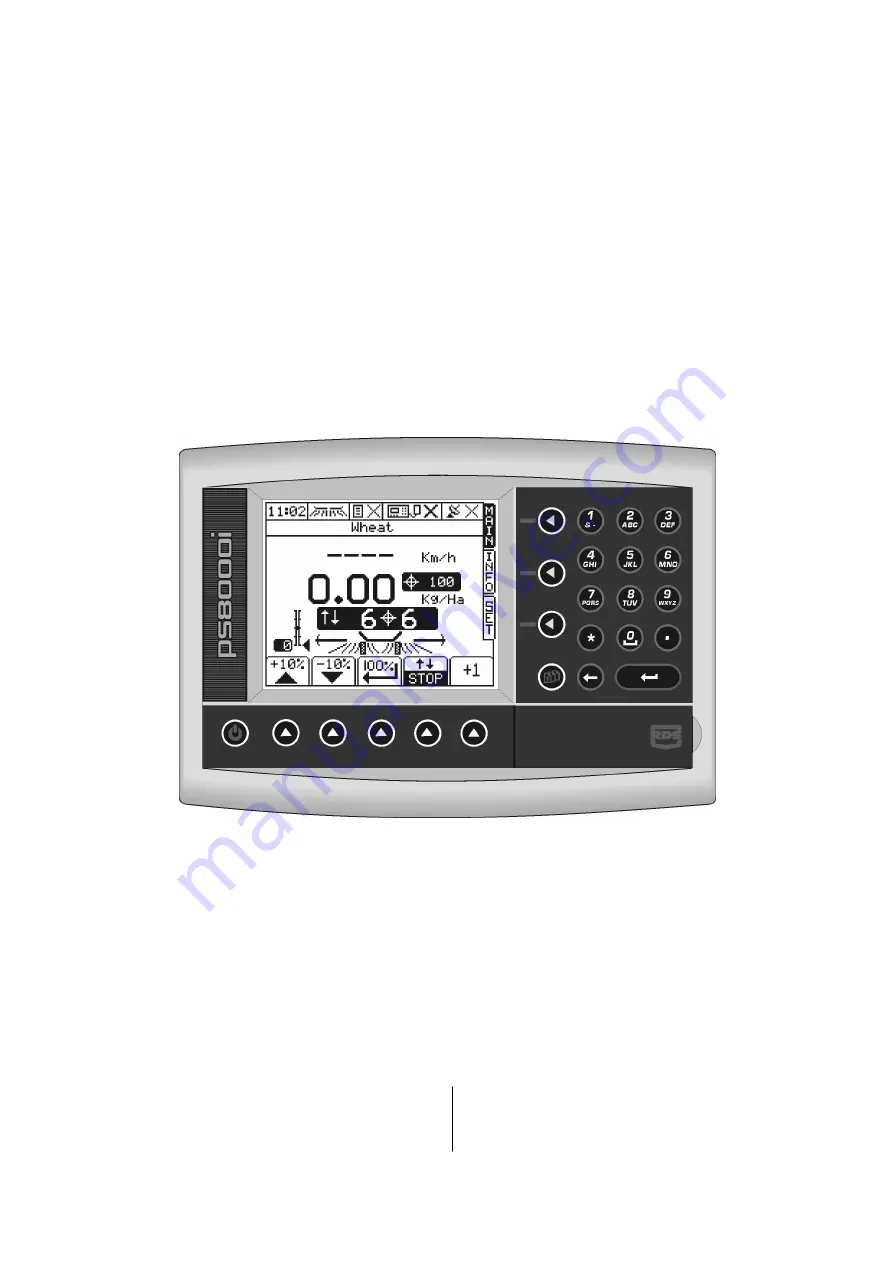
Pro-Series 8000i Athene
Variable Rate Drill Control
Operation
RDS Part No.:
Document Issue:
Software Issue:
S/DC/500-10-683 2.1 : 25.9.12 PS704-001 rev 01
Страница 1: ...1 Pro Series 8000i Athene Variable Rate Drill Control Operation RDS Part No Document Issue Software Issue S DC 500 10 683 2 1 25 9 12 PS704 001 rev 01...
Страница 2: ...d functions of the Precision Farming System the System are limited as set out in the specification of the System details of which are contained in the Help files and product literature and which must...
Страница 3: ...cing the bout number 10 2 5 3 Holding the bout number 10 2 5 4 Set Tramline Rhythm 12 3 CALIBRATION_________________________________________________________ 13 3 1 Working Width 13 3 2 Forward Speed 1...
Страница 4: ...6 Display GPS Status 23 5 2 Dynamic Data Logging 23 5 2 1 Start recording a Dynamic Job 23 5 2 2 Stop recording a Dynamic Job 23 5 3 Field Data Logging 24 5 3 1 Start recording Field Data 24 5 3 2 St...
Страница 5: ...ron MS to PS Athene Upgrade Figure 1 S CB 185 5 059 See section 2overleaf on wiring for work cutout Existing Installation S HU 268 5 227 Tramline Actuators Seed Variator Actuator Hopper Level Sensor F...
Страница 6: ...ut Wiring Marker Sensors Lefthand Marker Sensor connected to PL3 1 and PL3 4 Move the righthand Marker Sensor wires D from PL3 3 and PL3 4 to PL3 21 and PL3 22 Series to parallel Single Lift Sensor Co...
Страница 7: ...eration the control system is started and stopped automatically via magnetic sensors as the drill is put into and taken out of work The sensor is triggered by the operation of the markers 1 4 Menu key...
Страница 8: ...ation Accumulation NOTE The Data Card and GPS icons are only displayed when these functions are enabled via the SETUP menu 2 2 Drilling menu The instrument will always default to the MAIN screen on st...
Страница 9: ...med NOTE Seed distribution can be stopped by pressing repeatedly until the variator output is zero and the target rate resumed by pressing once A calibration test is recommended for each seed type and...
Страница 10: ...urrent bout number e g if entering work on a bout other than bout 1 of the tramline sequence To display the current tramline rhythm and starting bout no select the SETUP screen and press the key figur...
Страница 11: ...PRO SERIES ATHENE VARIABLE RATE DRILL CONTROL 11...
Страница 12: ...ical asymmetrical left or asymmetrical right rhythm selectable Two special asymmetric rhythms can be selected to suit the following drill sprayer width combinations 10 pass 4m drill 10m sprayer 6m dri...
Страница 13: ...t you can 1 Check the coefficient is still in memory The first level selected should be 3 330 m pulse 2 Perform a test over 100 metres as follows The unit will display the new coefficient It should no...
Страница 14: ...om the T Factor which is determined by performing a Seed Calibration Test edit the data as required Press to edit the seed names 3 3 2 Seed Calibration Before each drilling select the appropriate memo...
Страница 15: ...ing to the seed drill width m 2 50 3 00 3 50 4 00 4 50 5 00 5 50 6 00 6 50 tr 60 50 43 37 5 33 3 31 25 30 25 22 5 The display will show the accumulated no of turns of the seed shaft the accumulated ar...
Страница 16: ...ting RDS PRINTER ICP200 Printing Field Summary data Calibration data PC DOWNLOAD Output via cable to PC RDS PF MODULE Enables the internal Data Card Module OEM RATE CONTROLLER e g JD GREENSTAR Third p...
Страница 17: ...slot on your PC 2 Double click on this drive to access the card and the folder Rds_data xxx 3 From the File menu in Explorer download yield data files or upload treatment plan files using the normal...
Страница 18: ...5 minutes for the receiver to automatically establish its position Subsequently the unit should establish position more quickly NOTE The GPS icon at the top of the display indicates the status of the...
Страница 19: ...he value set for the previous job will appear on the Job Startup page It then becomes the responsibility of the operator to change the value via the key if so desired In nornal operation it is less li...
Страница 20: ...ence a full VRT application For a and b a full application record of the actual application is generated and saved on the Data Card The associated work record file can be viewed in the mapping treatme...
Страница 21: ...press 6 Wait while the work plan file is loaded and a work record file is created on the Data Module Once the plan is loaded the RUNNING A PLANNED JOB page appears and displays the tag list See secti...
Страница 22: ...ext F function appears If you do not need to programme any of them simply press at any time to start logging NOTE If a function on the Function Names Values page in the setup menu is set to Clear Stor...
Страница 23: ...g this data to a specific location The associated Dynamic Logging file is saved onto the Data Card Module 5 2 1 Start recording a Dynamic Job 1 Press the INFO key and then the key The screen will disp...
Страница 24: ...status the number of jobs job summaries stored in memory and the status of the data card module 2 Press the START key The JOB STARTUP page is displayed Select the logging option 3 LOG SUMMARY ONLY Whe...
Страница 25: ...bled Job Number Start Date Start Time End Time Job Duration Channel No Machine ID Name Farm No Field No Product Crop Cal Factor Area Work Rate Quantity spread Quantity loaded Average Application Rate...
Страница 26: ...complete from the menu select Transfer Capture Text Stop The data has now been saved to the designated file 8 This file may now be opened as a text file in a text editor e g Word Notepad etc and can...
Страница 27: ...RILL CONTROL 27 5 4 4 Printing Data to a Printer Ref Table 1 p 14 for port settings Accept the default TEXT mode for printing and the job summary or summaries print out as a job ticket with space for...
Страница 28: ...l Length 56mm Type Digital Linak Actuator P mm 2 00 Control Work Reg Reg ON OFF 2 Technician Config 1 Boom Cutout Inputs Master Cutout Normal Inverted Boom Inputs Normal Inverted Cutout Pulled Up Pull...
Страница 29: ...to Store A 4 PIN Change 4 General PF Setup 1 Logging Interval Log by Time Dist 2s 6m 2 Tag Names 3 Function Name Value F1 F12 4 GPS Antenna Offset x y 0 0 m 5 GPS Baud Rate 4800 9600 19200 6 Ports Se...
Страница 30: ...ABLE RATE DRILL CONTROL 30 Document History Issue 1 13 3 12 Original issue Issue 2 14 8 12 P 5 Add wiring instruction for drills with single lift sensor Issue 2 1 25 9 12 Ref CRQ 4247 p 6 Correction t...