


PROFESSIONAL AUDIO MIXER
4
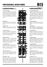
FRONT PANEL
VORDERSEITE
A. MONO INPUT CHANNELS
1. Mic Input
The microphone input to each channel
strip is made through a standard 3-pin
female Mic connector. The XLR (3-pin)
balanced input accepts microphone-level
signals and also features a swit48
V phantom power supply for condenser
microphones.
2. Line Input
The Line In connection for each channel
strip is located just below the Mic connec-
tor, and is made through a _” phone jack.
NOTE: You can use only either the
microphone or the line input of a chan-
nel at any one time.
3. Channel Insert Jack
Allows interface to external signal proces-
sing devices or direct channel output. This
patch point allows you to insert a com-
pressor, equalizer or any other signal pro-
cessing device into any of the input chan-
nel strips.
4. Low Cut Switch
The 75 Hz 18 dB/octave low-cut filter eli-
minates unwanted subsonic frequencies,
while still allowing full use of the low equa-
lization control (9).
5. Line Trim / Mic Gain
Simultaneously adjusts the Mic input gain
to accept signals from -15 dBm to -55
dBm, and trims the line input to accept si-
gnals from +5 dBm to -35 dBm.
6. High Equalization
Pr/-15 dB of shelving equalization
control to boost or cut high frequency si-
gnals 12 kHz and above.
7. High Mid Equalization
The high mid EQ section is a peaking/dip-
ping equalizer with a fixed center frequen-
cy of 3 kHz and a range of +/-12 dB.
8. Low Mid Equalization
The low mid EQ section is a peaking/dip-
A. MONO EINGANGSKANäLE
1. Mic-Eingang
Der Mikrophon-Eingang zu jedem Kanal
wird durch einen 3-poligen XLR-Stecker
hergestellt. Der symmetrische XLR-Ein-
gang akzeptiert Signale mit Mikrophon-
Pegel und verfügt außerdem über zu-
schaltbare Phantom-Power (+48 V) für
Kondensatormikrophone.
2. Line-Eingang
Der Line-Eingang der einzelnen Kanäle
befindet sich direkt unterhalb des Mic-Ein-
gangs. Der Anschluss erfolgt über einen
6,3 mm Klinkenstecker.
HINWEIS: Es kann immer nur jeweils ein
Eingang pro Kanal verwendet werden,
entweder Mic oder Line.
3. Channel Insert-Buchse
Dient zur Ankopplung eines externen Si-
gnalprozessors oder als direkter Kanal-
ausgang. Diese Verbindungsstelle ermög-
licht das Einschleifen eines Kompressors,
Equalizers oder anderen Geräts zur Si-
gnalbearbeitung in jeden einzelnen Kanal.
4. Low Cut-Schalter
Der Low Cut-Filter (75 Hz, 18 dB/Oktave)
beseitigt nicht gewollte Unterschallfre-
quenzen. Der „Low Equalization“-Regler
(9) kann jedoch weiterhin in vollem Umfang
benutzt werden.
5. Line Trim / Mic Gain
Stellt den Mic Input Gain so ein, dass Si-
gnale zwischen -15 dBm und -55 dBm an-
genommen werden. Gleichzeitig wird der
Line-Eingang auf eine Signalakzeptanz
zw5 dBm und -35 dBm angegli-
chen.
6. High Equalization
Ermöglicht die Anhebung oder Absenkung
der hohen Frequenzen (12 kHz und höher)
um +/-15 dB.
7. High Mid Equalization
Ermöglicht die Anhebung oder Absenkung
der hohen Mitten um die festgelegte zen-
trale Frequenz 3 kHz um +/-12 dB.
8. Low Mid Equalization
Ermöglicht die Anhebung oder
A
F
B
G
C
H
D
I
E
J
K
M
N
O
P
Q
R
L