RCA BRM350D Series Скачать руководство пользователя страница 3

3

Copyright © 2020 RCA Communications Systems   

www.RCACommunicationsSystems.com

Communications Systems

BRM350D Digital Mobile

Two-Way Radio

INSTRUCTION MANUAL

Transceiver Installation:
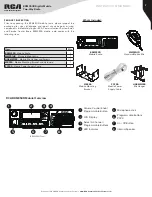
Tools Needed:

•  Electric Drill with 6mm bit or above

•  Philips Head Screwdriver

•  Hex Socket Sleeve (used for mounting 5mm X 16mm self-tapping 

screw)

When installing your transceiver, be sure to select a safe, convenient 

location. If you’re installing inside your vehicle, choose a location that 

minimizes danger to your passengers and yourself while the vehicle is in 

motion. Consider installing the unit so that knees or legs will not strike the 

unit during vehicle operation. Try to pick a well ventilated location that is 

shielded from direct sunlight for your installation location.
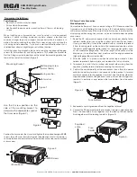
Install the mounting bracket in the vehicle using the supplied self-tapping 

screws (4), flat washers (4), and spring washers (4). Position the bracket so 

that the 3 long screw hole positions on the side of the mounting bracket are 

towards the rear of the bracket. (Figure 1)

Self-tapping screw

(5mm x 16mm)

Spring washer

Flat washer

Figure 1

Mounting Bracket

Use the 3 screw positions on the 

side of the mounting bracket to 

determine the appropriate angle of 

the transceiver. (Figure 2) 

Figure 2

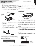
Position the transceiver, then insert and tighten the supplied hexagon SEMS 

screws (4) and flat washers (4). (Figure 3) Double check that all hardware is 

securely fastened to ensure that vehicle vibration will not loosen the bracket 

or transceiver.

SEMS Screws

Figure 3

(Radio back)

DC Power Cable Connection
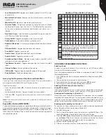
Mobile Operation

Your vehicle battery must have a nominal rating of 12V. Never connect the 

transceiver to a 24V battery. Be sure to use a 12V vehicle battery that has 

sufficient current capacity. If the current to the transceiver Is insufficient, the 

display may darken during transmission, or transmit output power may drop 

excessively.
1.  Route the DC power cable supplied with the transceiver directly to the 

vehicle’s battery terminals using the shortest path from the transceiver. 

If using a noise filter, it should be installed with an insulator to prevent 

it from touching metal on the vehicle. We recommend you do not use 

the power outlet/cigarette lighter socket as some power outlets have 

an unacceptable voltage drop. The entire length of the cable must be 

dressed so it is isolated from heat, moisture and the engine secondary 

(high voltage) ignition system/cables.

2.  After the cable Is In place, wrap heat-resistant tape around all fuse 

holders to protect it from moisture and tie down the full run of cable.

3.  To prevent the risk of short circuiting, disconnect other wiring from the 

negative (-) battery terminal before connecting the transceiver.

4.  Confirm the correct polarity of the connections, then attach the power 

cable to the battery terminals; red connects to the positive (+) terminal 

and black connects to the negative (-) terminal. Use the full length of the 

supplied cable without cutting off excess even If the cable is longer than 

required. In particular, never remove the fuse holders from the cable. 

(Figure 4)

Figure 4

Fuse holders

5.  Reconnect any wiring removed from the negative terminal.
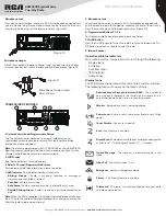
6.  Connect the DC power cable to the transceiver’s power supply connector. 

Press the connectors firmly together until the locking tab connectors 

firmly together until the locking tab clicks. (Figure 5)

Figure 5

Supplied 

cable

Fuse 

holder

Содержание BRM350D Series

Страница 1: ...ing to a Radio Call 7 Receiving Responding to a Group Call 7 Receiving Responding to a Private Call 8 Receiving an All Call 8 Monitoring a Channel Analog 8 Making a Radio Call 8 Making a Call With Channel Selector Buttons 8 Making a Private Call 8 Making an All Call 8 Making Group Private Call W 1 Touch Button 8 Emergency Operation 8 Initiating Responding to Emergency Alarm 9 Exiting Emergency Mod...

Страница 2: ... comes with the following items Item Qty BRM350D Mobile Radio 1 MM301HD Standard Mobile Mic 1 HGRMM300 Mobile Mic Hanger and Screws 1 MB300 Mobile Mounting Bracket and Hardware 1 PC300 Mobile Power Supply Cable 1 BRM350D Mobile Radio MB300 Mobile Mounting Bracket PC300 Mobile Power Supply Cable HGRMM300 Mic Hanger MM301HD Standard Mobile Mic RCA BRM350DMobile Overview 1 Volume Control Knob Program...

Страница 3: ... must have a nominal rating of 12V Never connect the transceiver to a 24V battery Be sure to use a 12V vehicle battery that has sufficient current capacity If the current to the transceiver Is insufficient the display may darken during transmission or transmit output power may drop excessively 1 Route the DC power cable supplied with the transceiver directly to the vehicle s battery terminals usin...

Страница 4: ...RCA Dealer for assistance Fuse Location Fuse Current Rating Transceiver 15A Supplied Accessory DC Power Cable 15A CAUTION Only use fuses of the specified type and rating otherwise the transceiver can be damaged Note If you use the transceiver for a long period when the vehicle battery is not fully charged or when the engine is OFF the battery may become discharged and may not have sufficient reser...

Страница 5: ...data Note When the LED is solid green it indicates the radio detects activity over the air Due to the nature of the digital protocol this activity may or may not affect the radio s programmed channel 5 Microphone Jack For voice communications connect a 600 Ω microphone equipped with an 8 pin modular plug into the modular socket on the front of the main unit Press firmly on the plug until the locki...

Страница 6: ...PTT button indicating the channel is free for you to respond You will also hear the Channel Free Indication tone if your call is interrupted for example when the radio receives an Emergency Call Select A Channel Press or to switch between channels Channels can be configured as analog or digital channel Your radio has features that are available in both analog and digital mode The minor differences...

Страница 7: ...ers require that you press a button multiple times The table shows the number of times a button needs to be pressed to generate the required character Key 1 2 3 4 5 6 7 8 9 10 11 12 13 1 1 2abc A B C 2 3def D E F 3 4ghi G H I 4 5jkl J K L 5 6mno M N O 6 7pqrs P Q R S 7 8tuv T U V 8 9wxyz W X Y Z 9 0CAPS 0 NOTE Press to enter 0 and long press to activate the CAPS lock Another long press to turn off...

Страница 8: ...k clearly into the microphone 4 Release the PTT button to listen 5 If there is no voice activity for a predetermined period of time the call ends The radio returns to the screen you were on prior to initiating the call Making a Private Call 1 Use the Channel Selector Buttons to select the channel with the active subscriber alias or ID 2 Press the PTT button to make the call The LED lights up solid...

Страница 9: ... a tone sounds to indicate target radio not available 7 Pressing the P4 button while the radio is waiting for acknowledgment and the radio terminates all retries and exits Radio Check Remote Monitor Use the Remote Monitor feature to turn on the microphone of a target radio subscriber alias or IDs only No audible or visual indication is given to the target radio You can use this feature to monitor ...

Страница 10: ...rn Off and press to select The display shows Text Message Tone Off and a appears left of Turn Off Call Log Features Your radio keeps track of all recent outgoing answered and missed Private Calls Use the call log feature to view and manage recent calls You can Store an ID from the Call Log to Contacts or Delete it The Call Log lists are Missed Answered and Outgoing Note When you select a Call List...

Страница 11: ...fails to send the radio returns you to the Resend option screen Sending a Quick Text Message Your radio stores a maximum of 10 Quick Text messages as programmed by your RCA Communications Systems dealer While Quick Text messages are predefined you can edit each message before sending it 1 Press VK to access the menu 2 Press or to navigate to Messages 3 Press or to Quick Text and press VK 4 Press o...

Страница 12: ... 3 Press or to navigate to Inbox and press VK to select 4 Press VK to select current message and press VK to select Press VK again to access the sub menu to Reply Forward or Delete the message 5 Press or to navigate to Delete and press VK to select 6 Press or to navigate to Delete and press VK to select 7 At Delete Message press or to navigate to Yes and press VK The display shows Message Deleted ...

Страница 13: ... scan list Note If set as priority the Priority icon appears left of the member s alias indicate whether the member is on a Priority 1 or Priority 2 channel list You cannot have multiple Priority 1 or Priority 2 channels in a scan list There is no priority icon if priority is set to None Scan Instructions and Methods When a scan is initiated your radio cycles through the programmed scan list for t...

Страница 14: ...display shows Auto On Press VK to enable the display backlight and the display shows Backlight Auto On OR If the display shows Turn Off press VK to disable the display backlight and the display shows Backlight Turn Off Note The display backlight and keypad backlight are automatically turned off if the LED indicator is disabled Talkaround This feature toggles between repeater and talkaround direct ...

Страница 15: ... and dust Avoid subjecting the radio to corrosives solvents or spirits Make sure the radio is completely dry before use Symptom Solution Radio will not power on 1 Check the power connections to make sure they have a solid connection 2 Check for one or more blown fuse s Radio is on but you cannot hear voice transmissions or they are not very loud 1 Turn the volume control knob to maximum volume 2 M...

Отзывы: