TC3 “O” V2
RC Product Designs
Page 8
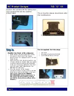
Ø
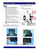
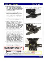
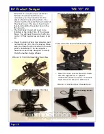
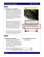
Mount the Tie Bar part number DC-008
with the provided 4-40 x 3/8” Flat Head
screw over the RH steering crank. Need to
add a #4 washer between tie bar and bell
crank.
(As shown in picture 4).
Tightened
the screw all the way in, then back off
screw a 1/8 of a turn so that the tie bar
rotates freely.
Ø
Install your steering links using the
turnbuckles and ball cups of your choice.
Each link should measure approx. 2.57”
(65 mm) in length from end to end. We
recommend you use a trapped end
cup/eyelet to attach servo link to the bell
crank. (More on that on step 7).
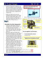
Assemble the Front Suspension:
Ø
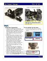
Mount the modified pivot blocks (part
number DC-016), starting with the
rearward first using the 2 supplied 4-40 x
½ ” Flat Head screws.
Picture 5.
Ø
You need to mount two 1/8” diameter
inner hinge pins. Insert the front A-Arms
(part number DC-013B) into the inner
hinge pin.
Ø
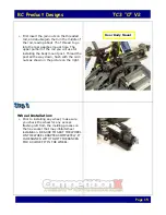
Be sure to modify and install a Rear
Bumper (Associated part number 3900) in
the front of the chassis as you assemble
the car. This bumper needs to be cut to
clear the gearbox. Also, the forward holes
must be elongated inboard to accept the
front arm mount which has a shorter span
length between the mounting holes.
(See
the picture on the right).
Ø
Mount the modified front bumper with the
modified forward front pivot block into the
inner hinge pin. Secure the pivot block
with the 2 provided 4-40 x ½” FH screws.
Ø
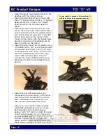
Mount the assembled front differential
gearbox, and secure it with the 4 supplied
4-40 x ½” Flat Head screws.
(Example
shown on picture 6).
Ø
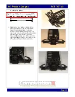
Install the front shock tower mount to the
top of the transmission case. Shim the low
side accordingly with the provided Delrin
spacer. Secure the shock tower mount
with 3 4-40 x 3/8” and 1 4-40 x 5/8”
Socket Head screws.
(As shown on pic. 7)
Picture 3
Picture 4: Tie Bar & Steering Bell Crank Installed
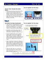
Tools required for this step:
Ø
1/16” Allen Wrench or Driver
Ø
3/32” Allen Wrench or Driver
Ø
Dremmel tool
Elongate the two forward holes in the inboard
direction to fit front modified arm mount.
Eliminate Inner Holes
Install (0.30”)
long spacer
and secure
with 7/8”
long screw.
Install Tie Bar in
forward/inboard hole.
Install black
spacer DC-
007B on large
diameter
post.
Install trapped
end/eyelet cup
on this end.
Make sure that the upper surface of the
Aluminum nut is below the surface of the
threaded Aluminum post.


