TC3 “O” V2
RC Product Designs
Page 14
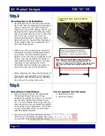
Steering Servo Installation:
Ø
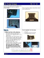
Use the Delrin servo mounts part number
DC-017B, with the appropriate Associated
spacers, based on your servo brand, to
install your servo first. (Please refer to the
Associated TC3 Instruction Manual). Make
sure you install the servo horn in this step
too. Try to use a long servo horn for
improved clearances to the drive shaft.
Secure the servo mounts from the bottom
of the chassis with the 2 supplied 4-40 x
3/8” Flat Head screws.
Ø
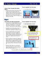
Install your servo steering link using the
turnbuckle and ball cup/trapped eyelet of
your choice. The link should measure
approx. 2.76” (70 mm) in length from end
to end. Use the provided 0.3” spacer on
the backside of the bell crank to increase
clearance of the steering link to the
driveshaft. Use the needle nose pliers to
pop in the ball cups on the ball studs.
Ø
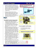
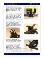
When adjusting the total steering throw of
the system, pay attention to the inboard
ball cups in the steering links so that they
do not touch the center drive cup.
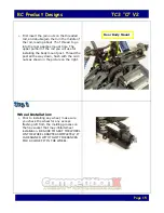
Body Mount Installation:
Ø
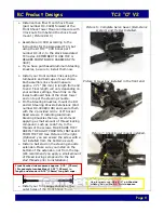
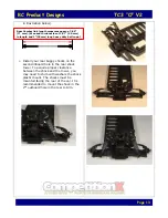
We recommend you use the Associated
“Front Body Mount” kit for all three
positions to support the body or you could
use the aftermarket Parma Body mount
kit. You can actually choose any kind you
want as long as you can adjust the height
of the body to your preference. The choice
is yours. (Example shown on next page
with Associated mounts).
Ø
We have provided 4-40 threaded rod and
nuts, so you can create the assembly once
you pick the body mounts of your choice.
Tools required for this step:
Ø
Needle Nose Pliers
Ø
3/16” Nut Driver
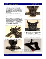
Black Delrin Servo mount installed in
chassis.
Note: Servo not shown installed in
picture. Must install servo to mounts
first, then to install assembly to chassis.
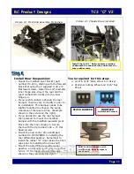
Servo Steering link length measures approx.
2.76” (70 mm). We used a turnbuckle of 1.57”
(40 mm) in length and 1”(25mm) long heavy duty
ball cup in one end and a trapped eyelet in the
other.


