background image

Included angle

1.

Turn the power source on and select the MMA function


with the MIG/MMA selector switch. (MMA IS ARC/STICK)

2. Polarity

Two  sockets  are  available  on  this  welding


machine. 

For  MMA welding  the  electrode  holder  is


shown

  to


be  connected  to  the positive  socket,


while  the 

earth  lead  (work  piece)  is  connected to


the  negative 

socket,  this  is  known  as  DC+  polarity.


However 

various  electrodes  require  a  different


polarity  for 

optimum  results and  careful  attention


should  be  paid 

to  the  polarity,  refer  to  the electrode


manufacturers 

information  for  the  correct


polarity.

DC+ Electrode connected to 

 output socket. 

DC- Electrode connected to 

 output socket.

(3)

 Set the welding current using the amperage control 

dial.

(6)

Hold the electrode slightly above the work

maintaining the arc while travelling at an even speed.

(4)

Place the electrode into the electrode holder and

clamp tight.

(7)

 To finish the weld, break the arc by quickly snapping 

the electrode away from the work piece.

(5) 

Strike the electrode against the work-piece to

create an arc and hold the electrode steady to maintain 
the arc.

(8) 

Wait for the weld to cool and carefully chip away

the slag to reveal the weld metal below.

1

2(+)

2(-)

11

SET UP FOR STICK (MMA) 

WELDING

Содержание JRW145D

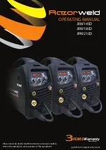
Страница 1: ...d understand this instruction manual carefully before the installation and operation of this equipment YEARS Warranty Power Source 3 OPERATING MANUAL JRW145D JRW180D JRW210D JASIC Technologies America...

Страница 2: ...history of welding knowledge and expertise giving vital input towards ensuring that our machines deliver control and performance to the utmost professional level We employ an expert team of profes si...

Страница 3: ...nert Gas Welding 25 26 Basic MIG Welding Guide 27 30 Installation Operation for TIG Welding 31 32 TIG Fusion Technique 33 Tungsten Electrodes Preparation 34 35 TWC2 MIG Torch Parts Breakdown 36 37 SPG...

Страница 4: ...in 19 1x7 3x14 6 Weight Machine Ibs 28 MIG TIG AND ARC Welding machine Latest IGBT inverter technology MIG MAG with Gas and Gasless wire function Excellent MIG welding with CO2 gas mixed gas Euro styl...

Страница 5: ...achine ensuring smooth and trouble free welding and backed up by a big 3 year warranty Our Smart set function allows you to dial in your preferred wire size and gas mixture and you are ready to start...

Страница 6: ...Our Smart set function allows you to dial in your preferred wire size and gas mixture and you are ready to start welding The machine comes complete with Torch Regulator Adaptor and Arc lead set A rea...

Страница 7: ...ut power cable for wear and tear replace the cable immediately if damaged bare wiring is dangerous and can kill Do not use damaged under sized or badly joined cables Do not drape cables over your body...

Страница 8: ...cause gas cylinders are normally part of the welding process be sure to treat them carefully CYLINDERS can explode if damaged Protect gas cylinders from excessive heat mechanical shocks physical damag...

Страница 9: ...ture inside the equipment The machine will be ready for use again when the internal temperature reaches safe level 2 3 Over Voltage Supply Regarding the power supply voltage range of the machine pleas...

Страница 10: ...Output terminal 8 Euro MIG TIG Torch Connector MIG MAG 9 Output terminal 10 SpoolGun Power Supply Connection 1 2 3 6 5 BACK PANEL LAYOUT 11 Power switch 12 Gas Inlet 13 Fan 14 Input power cable 15 Dat...

Страница 11: ...ctrode manufacturers information for the correct polarity DC Electrode connected to output socket DC Electrode connected to output socket 3 Set the welding current using the amperage control dial 6 Ho...

Страница 12: ...arc into the molten pool and becomes the deposited weld metal The deposit is covered and protected by a slag which comes from the electrode coating The arc and the immediate area are enveloped by an a...

Страница 13: ...welding in down hand fillet horizontal or overhead the angle of the electrode is generally between 5 and 15 degrees towards the direction of travel When vertical up welding the angle of the electrode...

Страница 14: ...tion is selected press trigger Arc starts release trigger Arc stops burnback operation is automatic and preset When 4T operation is selected press and release trigger Arc starts press and release trig...

Страница 15: ...alve and set the flow rate to between 11 21cfh 16 Set the welding parameters using the wire feed and voltage control knobs 17 Or use Smartset Smartset is a predefined setting based on Gas and wire use...

Страница 16: ...ed into a cylinder to form the finished wire The wire cannot take too much pressure from the top roller as it can be crushed and deformed if too much pressure is applied A knurled drive roller has bee...

Страница 17: ...tment if required Carefully retighten the locking nut and screw to hold the new position NOTE MIG 180 145 not geared 4 Snip the wire carefully be sure to hold the wire to prevent the spool uncoiling C...

Страница 18: ...ct the earth lead to Positive socket 3 Connect the weld power lead to Negative socket 4 Turn the power source on and select the MIG function with the MIG TIG MMA selector switch 5 Set torch operation...

Страница 19: ...hrough to the torch neck release the inch button when the wire exits the torch neck 13 Fit the correct sized contact tip and feed the wire through it screw the contact tip into the tip holder of the t...

Страница 20: ...way 7 Leaving the torch straight snip the liner approximately 1 8in past the end of the torch neck 8 Place the tip holder over the end of the liner and screw into the torch neck trimming it up tight...

Страница 21: ...ith the liner o ring 8 Push the liner firmly into the torch lead and tighten the liner retaining nut 9 Install a U groove drive roller of the correct size to match the wire diameter being used 2 Remov...

Страница 22: ...used NOTE MIG 180 145not geared 7 Place aluminum wire onto spool holder Feed the wire through the inlet guide tube on to the drive roller NOTE MIG 180 145 not geared 10 Connect the torch to the machin...

Страница 23: ...the MIG function with the MIG TIG MMA selector switch 7 Take the Spool Gun and push the Cover Release clip to unlock the wire feed spool cover 3 Connect earth lead to 1 Set Standard Spoolgun selector...

Страница 24: ...en the gas cylinder valve and set the flow rate to between 15 25 CFH 18 Set the welding parameters using the wire feed and voltage control knobs 18 17 Carefully open the valve of the gas cylinder set...

Страница 25: ...operties and corresponding advantages and limitations To perform MIG welding the basic necessary equip ment is a welding gun a wire feed unit a welding power supply an electrode wire and a shielding g...

Страница 26: ...at and force of the arc flattens out the droplet into the weld pool The heat of the arc melts the end of the wire slightly as it feeds towards the base metal The wire feed speed overcomes the heat of...

Страница 27: ...weld bead profile and degree of weld penetration Push Technique The wire is located at the leading edge of the weld pool and pushed towards the un melted work surface This technique offers a better v...

Страница 28: ...pe prevents undercut uneven penetration poor gas shield and poor quality finished weld Correct angle Not enough angle Too much angle good level of control over the weld pool even flat weld less contro...

Страница 29: ...resulting in a weld deposit of poor quality cold lap lack of fusion lack of joint penetration porosity large wide bead Too Slow Travel Speed Correct Travel Speed The correct travel speed keeps the arc...

Страница 30: ...welding zone from the atmosphere Too low flow will give inadequate coverage and result in weld defects and unstable arc conditions Too high flow can cause air to be drawn into the gas column and conta...

Страница 31: ...f the machine and tighten it 3 Insert the earth cable plug into the Positive socket on the front of the machine and tighten it 4 Insert the weld power cable into the negative socket on the front of th...

Страница 32: ...10 Lay the outside edge of the Gas Cup on the work piece with the Tungsten Electrode 1 16 in from the work piece Press the trigger button on TIG torch to start the gas flow 11 With a small movement r...

Страница 33: ...ool Travel direction Angle torch Add Tig filler wire Retract the filler wire Move the torch forward to the front of the weld pool Repeat the process gas shield TIG Welding Fusion Technique Manual TIG...

Страница 34: ...Ceriated Color Code Orange Ceriated tungsten electrodes AWS classification EWCe 2 contain a minimum of 97 30 percent tungsten and 1 80 to 2 20 percent cerium and are referred to as 2 percent ceriated...

Страница 35: ...thwise and thus grinding crosswise is grinding against the grain If electrodes are ground crosswise the electrons have to jump across the grinding marks and the arc can start before the tip and wander...

Страница 36: ...ption QTY EAN CODE PRW52 Gas Diffuser QTY x 2 0680474943975 TWC2 Gas Insulator Part Number Description QTY EAN CODE PRW32 Insulator QTY x 2 0680474943999 TWC2 Torch Nozzle Part Number Description QTY...

Страница 37: ...SPOOL GUN EXPLODED DIAGRAM SPGLBT200 37...

Страница 38: ...ig Torch Package Euro Connection SRE17 13FTE 150A AIR COOLED TIG WELDING TORCH Rating 150A DC 105A AC 35 ducy cycle Spare Parts Part Number Description 1 WP17 Torch head WP17F Torch head flexible 2 57...

Страница 39: ...iption 54N14 Gas lens ceramic 8 0mm 5 16 54N15 Gas lens ceramic 7 0mm 9 32 54N17 Gas lens ceramic 5 0mm 13 64 Compact Gas Lens Front End Parts Part Description TR0004 10 1 0mm x 175mm 0 040 x 6 57 64...

Страница 40: ...larger electrode Poor welding technique Use the correct welding technique or seek assistance for the correct technique Poor joint preparation Check the joint design and fit up make sure the material i...

Страница 41: ...stubbing during welding Possible Reason Suggested Remedy Holding the torch too far away Bring the torch closer to the work and maintain stick out of 5 10mm Welding voltage set too low Increase the vo...

Страница 42: ...gged the most common causes of bad feeding Try to clear the liner by blowing out with compressed air as a temporary cure it is recommended to replace the liner Wrong size liner Install the correct siz...

Страница 43: ...etal Remove materials like paint grease oil and dirt including mill scale from base metal Contaminated filler wire Remove all grease oil or moisture from filler metal Incorrect filler wire Check the f...

Страница 44: ...age point 6 Tighten clamps or fittings to eliminate gas leakage Important We strongly recommend that you check for gas leakage prior to operation of your machine We recommend that you close the cylind...

Страница 45: ...urer s Individual Warranty Contact the manufacturer for details Clause 3 This only Covers Manufactures defaults on all accessories for the first three months after date of purchase SELLER MAKES NO WAR...

Страница 46: ...and instruction material in as new condition as is reasonably possible in the circumstances JASIC Technologies America Inc Accepts no responsibility for products lost damaged or mislaid whilst in tran...

Страница 47: ...t Nipple Central Plug Printed Circuit Board Gun Plug House Cable Support Gas Con nector Handle To Suit PP36 with Knobs Electrodes Arc Leads Welding Cable Electrode Holder Earth Clamps TIG Welding Torc...

Страница 48: ...D E S I GNED TRUSTE D I N A U S T R A L I A U NIMIG WELDE R S 1985 85 19 EST Razorweld JASIC Technologies America Inc 25503 74th Ave S Kent WA 98032 USA Phone 1 253 859 6277 1253 859 6278 EMAIL SALES...

Отзывы: