


9
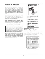
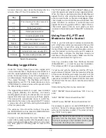
“DIP” Switch Settings on
Circuit Board
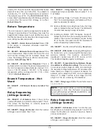
Four Stage Control
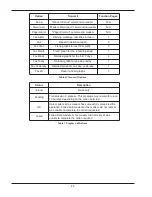
The four relay outputs are factory set for normally
closed dry contacts. These DIP switches are located
behind the terminal block, on the right side. The black
dots in the diagram indicate where to set the 20
switches for normally closed dry contacts. As shown,
all four outputs will be the same. Relay #1 is set on
SW1 positions 6 thru 10. Relay #2 is set on SW1 posi-
tions 1 thru 5. Relay #3 is set on SW2 positions 6 thru
10. Relay #4 is set on SW2 positions 1 thru 5.
These switches are factory set and should not need
adjustment.
The RayTemp can control up to 4 stages:
• Four single-stage heaters
• Two two-stage heaters
• One four-stage heater
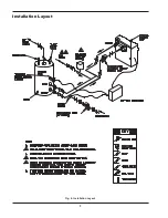
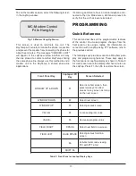
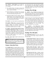
Two Stage Control
The two relay outputs are factory set for normally
closed dry contacts. These DIP switches are located
behind the terminal block, on the right side. The black
dots in the diagram indicate where to set the 10
switches for normally closed dry contacts. As shown,
both outputs will be the same. Relay #1 is set on SW1
positions 1 thru 5. Relay #2 is set on SW2 positions 1
thru 5.
These switches are factory set and should not need
adjustment.
The RayTemp can control up to 2 stages:
• Two single-stage heaters
• One two-stage heater
Connecting the Optional
“ELSA” Brand Modem
Raypak recommends the ELSA Microlink 56k modem
for data communication. This modem will work with
RayTemp and technical support will be provided if this
modem is installed with the correct cables. Raypak will
not be able to provide support if you use other modem
brands or build your own cables. In either case, we
strongly
recommend
that
you
test
the
RayTemp/modem connection in your office before
installing the system.
If possible, plan ahead, and have the phone line/jack
installed about two feet from the heater. Secure the
ELSA modem and connect the phone cable (that
comes with the modem) from the wall jack to the ELSA
modem jack labeled “Line”.
Connect the RayTemp cable 5-423 from the modem’s
8-pin connector to the RayTemp’s “Serial to RJ11”
adapter then connect the six-line data cable from the
adapter to the RayTemp’s six-pin “RJ11” port (see Fig.
7 on the next page). Plug in the modem’s power trans-
former and turn on the power switch. Testing is
covered in the next section.
Fig. 5: DIP Switch Setting on Circuit Board, 4-Stage
CAUTION:
Incorrect DIP switch settings may
damage the RayTemp! Make all adjustments with
ALL power off.
Fig. 6: DIP Switch Setting on Circuit Board, 2-Stage
CAUTION:
DO NOT connect a live phone line
directly to the RayTemp control. Doing so will
damage the internal communication circuit!
NOTE:
For On/Off and staged connections, consult
the water heater manual(s).


