


22
On P-106 heaters, splice into the red/white wire to connect
the time clock. For P-156 heaters the fireman’s switch
connection is located on the 14-pin header connected to
the digital control board. Splice into the red wire jumper
tagged “Where necessary add “Fireman’s” switch circuit
here” to connect the time clock.
The fireman’s switch connection on both heaters
must be a dry contact and must not supply power to
the heater. Powering the fireman’s switch connection
externally may damage the heater, and is not covered
by warranty.
P-156 heaters: Do not exceed 50' (15.2 m) of total wiring
using 18 AWG stranded copper wire rated for 221°F
(105°C) minimum.
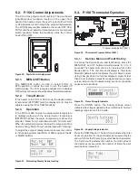
NOTE:
When using a time clock, the heater will display
“Clock/Fireman Sw” when the fireman’s switch is open,
indicating that the time clock has shut off the call for heat.
5.6. Post Start-Up Inspection
Do not use this heater if any part has been under water.
Immediately call a qualified service technician to inspect
the heater and to replace any part of the control system
and any gas control which has been under water.
N’utilisez pas cet appareil s’il a ete plonge dans l’eau,
meme partiellement. Faites inspecter l’appareil par un
technicien qualifie et remplacez toute partie du systeme
de controle et toute commande qui ont ete plonges dans
l’eau.
A
A
WARNING:
Should overheating occur or the gas
supply fail to shut off, turn off the manual gas control to
the appliance.
A
A
AVERTISSEMENT
: En cas de surchauffe ou si
l’alimentation en gaz ne s’arrete pas, fermez manueiiement
ie robinet d’arret de l’admission de gaz.
Feel the inlet and outlet pipes. Outlet pipe should be only
slightly warmer than the inlet. It should not be hot.
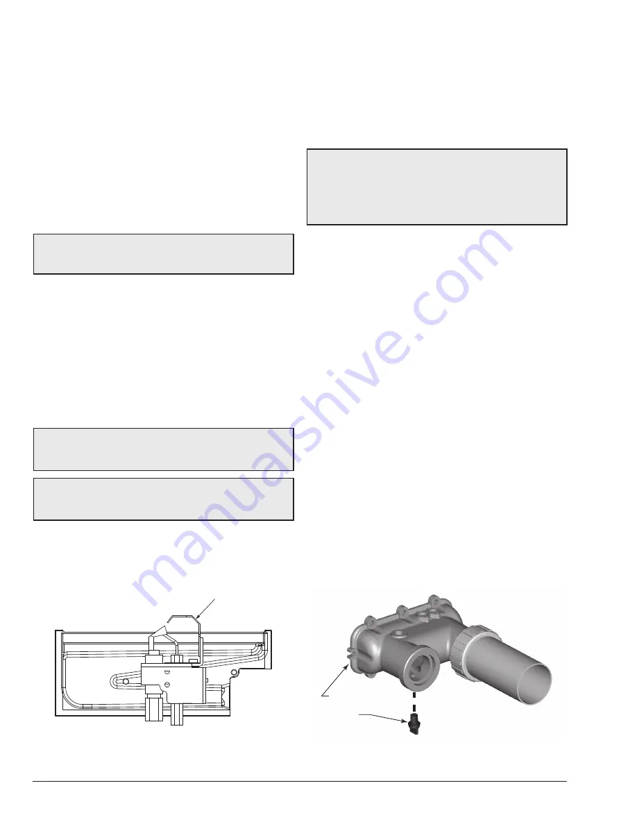
With the heater on, remove the door and make a visual
check of the burner.
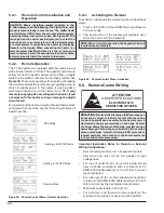
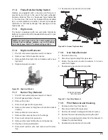
PILOT
Figure 33. IID Pilot Location
5.6.1. Cold Weather Operation
Moderate Climate
Heater operation can continue during short-term cold
spells. When temperatures are between 0° (-17°C) and
32°F (0°C), flow (continuous pump operation) must be
maintained.
A
A
CAUTION:
Do not use the heater to maintain water
temperatures just above freezing or for freeze protection.
When heater is used during freezing weather, care must
be taken to avoid freeze-ups. Continuous pump operation
is a must. Additional protection may be required. The
heater is not warranted against freeze-ups.
Cold Climate
Prolonged operation with water temperatures below 50°F
(10°C) is not recommended. When starting the heater with
water temperatures below 50°F (10°C), operate the heater
continuously until higher temperatures are reached.
Operating the heater for prolonged periods with pool
water below 50°F (10°C) can seriously damage the heater,
and is not covered by the warranty.
For cold climate areas, please follow the winterizing
procedures listed in the next section.
5.6.2. Winterizing the Heater
Heaters installed outdoors in freezing climate areas
may be shut down for the winter. Observe the following
procedure for winterizing the heater.
1. Turn off gas valve, manual gas valve, and electrical
supply to the heater.
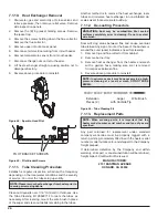
2. Open the drain plug located on the In/Out header,
under the water pipes.
3. Remove the 2 wires from the water pressure switch
and unscrew the water pressure switch to break any
vacuum in the system. Remove the pressure switch
and dry it before re-installing. Excessive moisture
in the pressure switch may freeze, damaging the
switch.
In/Out Header
Drain Plug
Figure 34. In/Out Header Drain Plug Location
Содержание 106
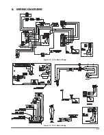
Страница 23: ...23 6 WIRING DIAGRAMS Figure 35 P 106 Heater Wiring Figure 36 P 156 Heater Wiring...
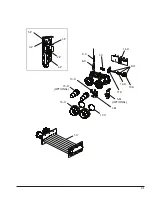
Страница 31: ...31 1 M 1 C 5 M OPTIONAL 9 C 8 H 10 H 11 H 12 H 13 H 14 H OPTIONAL 15 H 16 H 17 H 9 H 1 P 2 P 3 P 4 P 5 P 1 H...
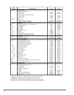
Страница 32: ...32 Natural 1 30mm 0 4 999 ft Propane 1 84mm 0 1 999 ft FOR ALTITUDES ABOVE THOSE LISTED CONSULT THE FACTORY...
Страница 34: ...34 NOTES...
Страница 35: ...35 NOTES...
Страница 36: ...www raypak com Raypak Inc 2151 Eastman Avenue Oxnard CA 93030 805 278 5300 Fax 805 278 5468 Litho in U S A...


