Raypak 106 Скачать руководство пользователя страница 21

21

NOTE:

 The remote wires must be connected to the 7-pin 

connector before the connector is plugged into the board.

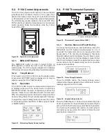
5.5.1.  2-Wire Remote Control (On-Off)

This application assumes that only one heating function 

(pool or spa) is required.
1.  Turn on power to the heater.
2.  For a 2-Wire Remote Control from a remote without 

its own sensor, push the MENU/SET button to the 

“POOL” or “SPA” mode and set the desired setpoint 

(eg. 102 °F (39°C) for Spa).

3.  For a 2-Wire Remote Control from a remote with its 

own sensor, push the MENU/SET button “POOL” or 

“SPA” mode and set the temperature to the highest 

setting available on the control. The actual setpoint 

will be controlled by the remote control.

4.  Turn  the  MENU/SET  button  to  “OFF”  and  remove 

power from the heater.

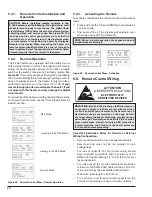
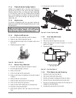
5.  On  the  “Remote  Interface  Harness”,  connect  the 

BLUE  wire  to  one  side  of  the  “REMOTE”  switch 

and connect the other side to either the ORANGE/

BLACK  wire  for  “SPA”  operation  or  the  BLACK/

ORANGE wire for “POOL” operation. See Figure 30

Pool Common

(BLK/ORN)

Spa Common

(ORN/BLK)

24VAC HOT

(BLU)

Figure 30.  7-Pin Remote Interface Harness

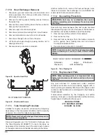
6.  Attach  wire  nut  on  unused  wire  to  the  “Remote 

Interface Harness.”

7.  Install the “7-Pin Remote Interface Harness” to the 

P8  connector  and  turn  power  “On”  to  the  heater. 

See Figure 31.

8.  For activation of the remote control, see "Activating 

the Remote" on page 20. 

5.5.2.  3-Wire Remote Control Using 

Three-Position Switch (Pool-Off-

Spa, or Low-Off-High)

1.  This application assumes that both heating functions 

(pool and spa) are required.

1.  Turn on power to the heater.
2.  Push  the  menu/set  button  to  the  “POOL”  or  “SPA” 

mode and set the desired temperature for each (eg. 

80°F (27°C) for Pool and 102°F (39°C) for Spa).

3.  Turn  the  MENU/SET  button  to  “OFF”  and  remove 

power from the heater.

Wire Nut - 

BLK/ORN - To Pool (COMM)

ORN/BLK - To Spa (COMM)

BLU - 24VAC

Figure 31.  2-Wire Remote Harness Installation on the P8 

Connector of the ATF Board

BLK/ORN - To Pool (COMM)

ORN/BLK - To Spa (COMM)

BLU - 24VAC

Figure 32.  3-Wire Remote Harness Installation on the P8 

Connector of the ATF Board

4.  On  the  “Remote  Interface  Harness”  connect  the 

BLUE  wire  to  one  side  of  the  “REMOTE”  switch 

and  connect  the  ORANGE/BLACK  wire  for  “SPA” 

operation  and  the  BLACK/ORANGE  wire  for  the 

“POOL” operation. See Figure 30

5.  Install  the  “Remote  Interface  Harness”  to  the  P8 

connector  and  turn  power  “ON”  to  the  heater. 

See Figure 32.

6.  For activation of the remote control, see "Activating 

the Remote" on page 20. 

5.5.3.  Time Clock/Fireman’s Switch

To operate the heater with a time clock, connect the timer 

to the fireman’s switch connection in the heater’s wiring. 

The time clock should be of the dual switch type and set to 

shut off the call for heat to the pool heater (chauffe-piscine) 

15 to 20 minutes prior to shutting down the pool pump. 
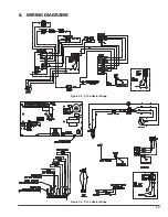
Содержание 106

Страница 1: ...ic Above Ground Pool Spa Heater Chauffe Piscine English French A AAVERTISSEMENT Assurez vous de bien suivre les instructions donn es dans cette notice pour r duire au minimum le risque d incendie ou d...

Страница 2: ...g changes Manual updated to the new format style Removed California Proposition 65 warning on pages 4 and 7 Replaced analog electronic with 106 156 on section 3 3 1 page 6 Replaced analog digital with...

Страница 3: ...n 10 4 5 Indoor Installation 10 4 6 Combustion and Ventilation Air Indoor Units Only 11 4 7 Gas Connections 12 4 8 Electrical Connections 15 4 9 240 Volt Installation Instructions 15 5 CONTROLS 16 5 1...

Страница 4: ...cal laws rules regulations or customs A AWARNING The heater shall not be located in an area where water sprinklers or other devices may cause water to spray through the cabinet louvers and into the he...

Страница 5: ...builder accredited pool shop or chemical supplier for the correct levels for your water 2 1 Automatic Chlorinators and Chemical Feeders All chemicals must be introduced and completely diluted into th...

Страница 6: ...mperatures by as much as 4 F 2 C 5 Persons with a medical history of heart disease circulatory problems diabetes or blood pressure problems should obtain a physician s advice before using spas or hot...

Страница 7: ...n the installation of this type of heating equipment and related system components Installation and service personnel may be required by some states to be licensed If your state is such be sure your c...

Страница 8: ...t will enable the heater to be serviced without removing any structure around the heater It is possible to reduce the clearances to combustible surfaces by protecting these surfaces as shown in table...

Страница 9: ...9 Figure 5 Florida Building Code Tie Down Method Amp Draw 120 Volt 240 Volt 4 2 Figure 4 Heater Dimensions...

Страница 10: ...the flue products exit the heater must be a minimum of 4 1 2 m below 4 1 2 m horizontally from or 1 0 3 m above any door window or gravity inlet into any building The top surface of the heater shall...

Страница 11: ...d the likelihood of condensate production in the vent Category I A heater which operates with a non positive vent static pressure and with a vent gas temperature that avoids excessive condensate produ...

Страница 12: ...ter A ACAUTION The heater and its manual shut off valve must be disconnected from the gas supply during any pressure testing of that system at test pressures in excess of 1 2 psig 3 5 kPa The heater a...

Страница 13: ...m 459 140 m Table capacities are based upon use of sch 40 black iron pipe For capacities using other materials consult local code Natural Gas 1000 BTU FT3 0 60 Specific Gravity 0 5 WC Pressure Drop Ga...

Страница 14: ...d be slightly warmer than inlet and comfort able to the touch If pipe is hot close bypass if cold open bypass 4 7 10 Pressure Relief Valve Installation To conform to local building codes it may be nec...

Страница 15: ...directly from the GFCI power source It is preferred to make connection to the load pump side of the time clock A AWARNING Risk of electrical shock More than one disconnect switch may be required to d...

Страница 16: ...t The switch functions as a means for turning the heater On or Off The thermostat is fitted with a means of limiting the upper temperature limit below the maximum level The knob stop adjustment ring s...

Страница 17: ...er is firing Water Temp will alternate with Heating To adjust the setpoint temperature make sure the control is in the appropriate mode POOL or SPA and push the UP or DOWN buttons Figure 21 Alternatin...

Страница 18: ...he digital display Press and hold both UP and DOWN buttons for 5 7 seconds until Faults Cleared appears This operation resets the Fault History file to 0 and clears all the stored faults Fahrenheit or...

Страница 19: ...C Flame w o CFH Board is sensing flame when both main and pilot valves are commanded shut PV Output Fault Pilot gas valve output is not in commanded state MV Output Fault Main gas valve output is not...

Страница 20: ...g in the POOL Mode Heating in the SPA Mode Remote Mode Figure 28 Remote Control Menu Remote Operation 5 4 3 Activating the Remote To activate or deactivate the remote function follow these steps 1 Pre...

Страница 21: ...f the remote control see Activating the Remote on page 20 5 5 2 3 Wire Remote Control Using Three Position Switch Pool Off Spa or Low Off High 1 This application assumes that both heating functions po...

Страница 22: ...e only slightly warmer than the inlet It should not be hot With the heater on remove the door and make a visual check of the burner PILOT Figure 33 IID Pilot Location 5 6 1 Cold Weather Operation Mode...

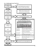
Страница 23: ...23 6 WIRING DIAGRAMS Figure 35 P 106 Heater Wiring Figure 36 P 156 Heater Wiring...

Страница 24: ...djust the pressure switch to compensate for the no flow static head If it is necessary to adjust the water pressure switch utilize the following procedure A ACAUTION Do not adjust the pressure switch...

Страница 25: ...7 1 7 Burner Tray Removal 1 Shut off main electrical power switch to heater 2 Shut off gas upstream of heater 3 Remove front door 4 Disconnect gas line from gas valve 5 Remove 3 screws holding the an...

Страница 26: ...xchanger ream tubes and immerse heat exchanger in non inhibited de scale solvent for severe scale build up 7 1 12 De sooting Procedure A ACAUTION Soot may be combustible Wet sooted surfaces completely...

Страница 27: ...nd 110 F 40 5 C and 43 3 C If no movement replace Air starvation Refer to installation instructions Improper venting Follow recommended installation instructions Insects or debris clogging burner inta...

Страница 28: ...o pressure then there is not enough moving water in the system or the gauge is broken Attempt to make the pump run at its normal flow rate Does the pilot spark after performing the above steps 1 The s...

Страница 29: ...stance k 261 1 199 0 153 1 118 8 93 0 73 3 58 3 51 0 If okay replace Circuit Board Sensor Failure Inspect thermister wires and connector at Terminal P1 Check resistance value of the thermister Referen...

Страница 30: ...S 3 S 2 M 3 M 4 M 1 J 2 J 2 J 3 J 4 J 4 J 1 V 2 V 3 V 4 V 11 M 12 M 1 B 10 S 5 S 6 S 7 S 8 S 9 S 9 S 3 B 6 C 8 C 9 C 2 H 3 H 4 H 5 H 6 H 6 H 7 H 7 H 2 C 3 C 10 M 9 M 8 M 5 V 5 C 4 S 7 C 4 C 10 C 9 IL...

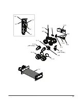
Страница 31: ...31 1 M 1 C 5 M OPTIONAL 9 C 8 H 10 H 11 H 12 H 13 H 14 H OPTIONAL 15 H 16 H 17 H 9 H 1 P 2 P 3 P 4 P 5 P 1 H...

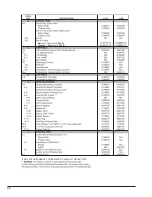
Страница 32: ...32 Natural 1 30mm 0 4 999 ft Propane 1 84mm 0 1 999 ft FOR ALTITUDES ABOVE THOSE LISTED CONSULT THE FACTORY...

Страница 33: ...4891F S SHEETMETAL 1 S Jacket Top 014892F 014893F 2 S Jacket Left 014894F 014895F 3 S Jacket Right 014896F 014897F 4 S Jacket Upper Front 014898F 014898F 5 S Jacket Lower Rear 014899F 014899F 6 S Flue...

Страница 34: ...34 NOTES...

Страница 35: ...35 NOTES...

Страница 36: ...www raypak com Raypak Inc 2151 Eastman Avenue Oxnard CA 93030 805 278 5300 Fax 805 278 5468 Litho in U S A...

Отзывы: