background image

28

*3-Button Remote

If provided with your garage door opener, the large button is
factory programmed to operate it. Additional buttons on any

S

AFETY

S

IGNAL

TM

3-Button remote or
mini-remote can be
programmed to
operate other 

Safety

Signal™

garage door

openers.

To Erase All Codes From

Motor Unit Memory

To deactivate any unwanted remote, first
erase all codes:

Press and hold the “learn” button on
motor unit until the learn indicator light
goes out (approximately 6-9 seconds).
All previous codes are now erased.
Reprogram each remote or keyless
entry you wish to use.

Your garage door opener has already been programmed at the factory to operate with your hand-held remote control. The door
will open and close when you press the large push button. 

Below are instructions for programming your opener to operate with additional 

S

AFETY

S

IGNAL

TM

remote controls.

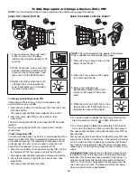
1. Press and release the purple “learn”

button on the motor unit. The learn
indicator light will glow steadily for 30
seconds.

2. Within 30 seconds, press and hold the

button on the hand-held remote

*

that

you wish to operate your garage door.

3. Release the button when the motor

unit lights blink. It has learned the
code. If light bulbs are not installed,
two clicks will be heard.

To Add or Reprogram a Hand-held Remote Control

USING THE “LEARN” BUTTON

USING THE SMART CONTROL PANEL™

LOCK

L

I

GHT

PROGRAMMING

NOTICE:

If this 

S

AFETY

S

IGNAL

TM

garage door opener is operated with a non-rolling code transmitter, the technical measure in

the receiver of the garage door opener, which provides security against code-theft devices, will be circumvented. The owner of
the copyright in the garage door opener does not authorize the purchaser or supplier of the non-rolling code transmitter to
circumvent that technical measure.

LOC

K

LIGHT

LOCK

LIGHT

LOC

K

LIG

HT

1. Press the Prog <Learn> button on the

Smart Control Panel™.

2. Press the Prog <Learn> button again

to confirm Learn Mode.

3. Press the button on the hand-held

remote that you wish to operate your
garage door.

4. When the motor unit lights blink, it has

learned the code. If light bulbs are not
installed, two clicks will be heard.

LOCK

LIGHT

LOCK

LIGHT

Содержание Safety Signal 3800RGD

Страница 1: ...checks of the opener are required to ensure safe operation The model number label is located behind the hinged door of your opener Do NOT exceed 10 complete cycles of door operation per hour GARAGE DO...

Страница 2: ...nit 6 Installation 7 16 Installation safety instructions 7 Position the opener 7 Attach the emergency release rope and handle 8 Install the power door lock 8 Attach the cable tension monitor Required...

Страница 3: ...below Must have minimum of 2 1 2 6 4 cm between the garage wall and the center of the torsion bar Must have minimum of 3 7 6 cm between the ceiling and the center of torsion bar Must have minimum of...

Страница 4: ...te cycles of door operation per hour To prevent possible SERIOUS INJURY or DEATH ALWAYS call a trained door systems technician if garage door binds sticks or is out of balance An unbalanced garage doo...

Страница 5: ...Connector Remote Light Opener Light with Hardware Bag Smart Control Panel LOCK L G I HT Carton Inventory Your garage door opener is packaged in one carton which contains the motor unit and the parts i...

Страница 6: ...t 12 14 ft lbs of torque Figure 2 NOTE For most installations the screws should be facing up for easy access Do not tighten set screws until indicated 6 Collar Screw Collar Screw Set Screw ASSEMBLY ST...

Страница 7: ...hnician if garage door binds sticks or is out of balance An unbalanced garage door might not reverse when required Operator MUST be mounted at a right angle to the torsion bar to avoid premature wear...

Страница 8: ...Overhand Knot Rope Motor Unit Emergency Release Cable To prevent possible SERIOUS INJURY or DEATH from a falling garage door If possible use emergency release handle to disengage door ONLY when garage...

Страница 9: ...ble it on the opposite side of the cable tension monitor 1 Position the cable tension monitor as shown Figures 1 and 2 The cable tension monitor should be located as close to the drum as possible NOTE...

Страница 10: ...en snap cover in place 3 For standard installations ONLY Run bell wire up wall and across ceiling to motor unit Use insulated staples to secure wire in several places Do NOT pierce wire with a staple...

Страница 11: ...total 7 Install the light lens by hooking one end of the lens over the hinge and pressing up on the other end to latch into place Figure 3 8 Plug in the light to outlet NOTE Light will not operate unt...

Страница 12: ...Install a 90o conduit or flex cable adapter to the 7 8 hole Reinstall opener to torsion bar Run wires through conduit cut to proper length and strip insulation Attach with wire nuts provided Properly...

Страница 13: ...he SPU as desired to a structural support ceiling joist or wall stud Attach the SPU to the support using the mounting holes on either side of the SPU Secure the SPU using the 1 1 2 lag screws 2 provid...

Страница 14: ...other across the door no more than 6 15 cm above the floor Either can be installed on the left or right of the door as long as the sun never shines directly into the receiving eye lens The mounting b...

Страница 15: ...with the lip hugging the back edge of the track as shown in Figure 1 If your door track will not support the bracket securely wall installation is recommended Wall installation Figure 2 and 3 Place th...

Страница 16: ...ng eyes will glow steadily if wiring connections and alignment are correct The sending eye amber indicator light will glow regardless of alignment or obstruction If the green indicator light in the re...

Страница 17: ...indicator light starts flashing slowly then release 2 Push and hold the black button until the door reaches the desired UP open position Figure 2 NOTE Check to be sure the door opens high enough for...

Страница 18: ...d to open and close your door The door must travel through a complete cycle UP and DOWN in order for the force to be set properly If the unit cannot open and close your door fully inspect your door to...

Страница 19: ...est The Protector System Press the remote control push button to open the door Place the opener carton in the path of the door Press the remote control push button to close the door The door will not...

Страница 20: ...n on the emergency release handle until a click noise is heard from the unit and lift the door manually To reconnect the door to the opener pull down the emergency release handle straight down a secon...

Страница 21: ...t Control Panel is activated Bulb size is A19 Bulb power is 100 watts maximum SAFETY SIGNALTM light feature Lights will also turn on when someone walks through the open garage door With a Smart Contro...

Страница 22: ...able the motion sensor when using the opener lights as working lights Otherwise they will turn off automatically if you are working beyond the sensors range Lock feature Designed to prevent operation...

Страница 23: ...non metallic surface This allows the sensor to recalibrate itself Dim LED lights Replace two 3V2016 batteries with same type 3V2016 coin cells No rapid LED blinking after pressing a button Replace tw...

Страница 24: ...to match the remote control code Refer to instructions on the motor unit panel Repeat with all Remote 4 The remote control has short range Change the location of the remote control in your car Check t...

Страница 25: ...le the power door lock 12 The opener won t operate due to power failure Manually open the power door lock Use the emergency release handle to disconnect the door The door can be opened and closed manu...

Страница 26: ...on the Smart Control Panel Pressing the Prog LEARN button again will allow the user to program an additional remote control to the opener Meaning This message will appear when the Prog learn button ha...

Страница 27: ...mentarily short across red and white terminals with jumper wire If motor unit activates replace door control wires Symptom Sending indicator light glows steadily receiving indicator light is dim or fl...

Страница 28: ...seconds 2 Within 30 seconds press and hold the button on the hand held remote that you wish to operate your garage door 3 Release the button when the motor unit lights blink It has learned the code If...

Страница 29: ...d hold the button The opener light will blink three times Release the button 2 Press the temporary 4 digit PIN you have chosen then press Enter The opener light will blink four times 3 To set the numb...

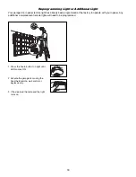
Страница 30: ...emote wall control or keyless entry 3 It has learned the code and the light turns on Reprogramming Light or Additional Light Your garage door opener remote light has already been programmed at the fac...

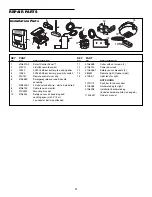
Страница 31: ...494 1 2 Conductor bell wire white white red 8 41A6104 Cable tension monitor 9 41C0902 Mounting bracket 10 41A5034 Safety sensor kit receiving and sending eyes with 3 9 m 2 conductor bell wire attached...

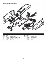
Страница 32: ...DESCRIPTION 1 41DJ001 Logic board complete with plate 2 41A6408 Absolute Encoder System 3 41C168 Transformer KEY PART NO NO DESCRIPTION 4 41A6095 Motor with bracket 5 41B122 Power cord 6 41A6348 5 Co...

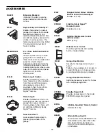
Страница 33: ...or modules 915LM Garage Door Monitor Sensor Additional accessory sensor for homes with multiple garage doors 916LM Standby Power Unit Provides backup power to the model 3800RGD garage door opener 475R...

Страница 34: ...34 OPERATOR NOTES...

Страница 35: ...35 OPERATOR NOTES...

Страница 36: ...are confirmed to be defective and covered by this limited warranty will be repaired or replaced at Seller s sole option at no cost to you and returned pre paid Defective parts will be repaired or rep...

Отзывы: