background image

Parts included

Quan-
tity

Connector A

Cable

Connector B

Length

T-piece

(A06028)

4

N/A

N/A

N/A

Backbone
terminator

(A06031)

2

N/A

N/A

N/A

SeaTalk

ng

Evolution cable kit (R70160)

Parts included

Quan-
tity

Connector A

Cable

Connector B

Length

Backbone cable
(

(A06036)

)

2

5m (16.4ft)

Power cable
(

A06049

)

1

1m (3.3ft)

Spur cable
(

A06040

)

1

1m (3.3ft)

ACU / SPX power
cable

(R12112)

(for powering
the SeaTalk

ng

backbone from the
autopilot system.

1

0.3m (1.0ft)

5–way connector

(A06064)

. Each

connector block
allows the
connection of up
to 3 compatible
devices. When
correctly
terminated, a
connector block
forms a complete
backbone.
Multiple connector
blocks can be
daisy-chained
together.

1

N/A

N/A

N/A

Spares and accessories

69

Содержание i60 wind

Страница 1: ...2016 Raymarine UK Limited 81342 3 Document number 07 2016 Date English EN INSTALLATION OPERATION INSTRUCTIONS i60 Instrument...

Страница 2: ......

Страница 3: ...pending or design patents pending Fair Use Statement You may print no more than three copies of this manual for your own use You may not make any further copies or distribute or use the manual in any...

Страница 4: ......

Страница 5: ...Wind vane transducer and rotavecta mounting 19 Chapter 4 Cables and connections 21 4 1 General cabling guidance 22 Cable types and length 22 Routing cables 22 Strain relief 22 Cable shielding 22 4 2 C...

Страница 6: ...g between true and apparent wind information 45 8 3 Illumination 46 Adjusting the backlight level 46 Adjusting the contrast i60 46 Group illumination 46 Chapter 9 Alarms 47 9 1 Alarms 48 Instrument al...

Страница 7: ...product contains high voltage Adjustments require specialized service procedures and tools only available to qualified service technicians There are no user serviceable parts or adjustments The operat...

Страница 8: ...ion or maintenance it must be replaced in the original position before the product is used Use only ferrites of the correct type supplied by Raymarine or its authorized dealers Where an installation r...

Страница 9: ...ts and workboats NOT covered by International Maritime Organization IMO and Safety of Life at Sea SOLAS Carriage Regulations Technical accuracy To the best of our knowledge the information in this doc...

Страница 10: ...10...

Страница 11: ...Chapter 2 Handbook information Chapter contents 2 1 Document information on page 12 2 2 Parts supplied on page 13 2 3 i60 Product overview on page 13 Handbook information 11...

Страница 12: ...i60 Depth Speed Wind system pack E70153 i50 Depth SeaTalkng instrument display P319 Thru hull Depth transducer i50 Speed SeaTalkng instrument display P120 Thru hull Speed and Temp transducer i60 Wind...

Страница 13: ...1 i60 Wind The i60 Wind instrument provides a 360 wind direction scale and can be used as a stand alone unit or as part of a SeaTalk or SeaTalkng network 2 i60 Close Hauled CH Wind The i60 Close haul...

Страница 14: ...14...

Страница 15: ...page 16 3 2 Compatible transducers on page 16 3 3 System protocols on page 17 3 4 Tools required on page 17 3 5 Selecting a display location on page 18 3 6 Product dimensions on page 19 3 7 Wind vane...

Страница 16: ...nance of the system The diagram should include Location of all components Connectors cable types routes and lengths 3 2 Compatible transducers Instrument Wind Vane transducer The wind vane transducers...

Страница 17: ...SeaTalk and SeaTalk2 devices can also be connected using the appropriate interfaces or adaptor cables as required NMEA 2000 NMEA 2000 offers significant improvements over NMEA 0183 most notably in spe...

Страница 18: ...ed in a location which allows proper routing and connection of cables Minimum cable bend radius of 100 mm 3 94 in is required unless otherwise stated Use cable supports to prevent stress on connectors...

Страница 19: ...any equipment which may shield the transducer or otherwise disturb the air flow Provide a horizontal mounting surface If a surface e g mast top is otherwise suitable but not horizontal make up a suita...

Страница 20: ...20...

Страница 21: ...overview on page 22 4 3 Direct Power Connection on page 23 4 4 SeaTalkng power supply on page 23 4 5 Transducer connections on page 26 4 6 iTC 5 connection on page 26 4 7 SeaTalkng connection on page...

Страница 22: ...t carrying AC and DC power lines antennae Strain relief Ensure adequate strain relief is provided Protect connectors from strain and ensure they will not pull out under extreme sea conditions Cable sh...

Страница 23: ...to power the SeaTalkng backbone as this can cause sudden voltage drops when the engines are started 2 The ACU 100 and SPX 5 cannot be used to power the SeaTalkng backbone SeaTalkng power connection po...

Страница 24: ...itably qualified professional marine electrician Implementation direct connection to battery SeaTalkng power cables may be connected directly to the vessel s battery via a suitably rated fuse or break...

Страница 25: ...Electrical Systems on Boats ABYC A 31 Battery chargers and Inverters ABYC TE 4 Lightning Protection Sharing a breaker Where more than 1 piece of equipment shares a breaker you must provide protection...

Страница 26: ...place those removed When fitting the new spade connectors prepare the cables as detailed below 1 Prepare the cable as shown in 1 above 2 Fold back the wire strands and insert into the new spade connec...

Страница 27: ...pply 5 EV unit 6 SeaTalkng 5 way connector 7 Rudder reference transducer 8 iTC 5 converter 9 Depth transducer 10 Wind transducer 11 Speed transducer Example SeaTalkng SPX system with transducer pods I...

Страница 28: ...ucer 10 SeaTalk Course computer providing 12 V dc power to SeaTalk network 11 ST6002 SeaTalk pilot controller 12 12 24 V dc power supply SeaTalk power protection The power supply must be protected by...

Страница 29: ...Chapter 5 Mounting Chapter contents 5 1 Mounting on page 30 5 2 Front bezel on page 31 Mounting 29...

Страница 30: ...gsaw cut along the inside edge of the cut out line 5 Ensure that the unit fits into the removed area and then file around the cut edge until smooth 6 Drill any required holes as indicated on the mount...

Страница 31: ...g so may cause damage 1 Using your fingers pull the bezel away from the unit at the top and side as shown in 2 The bezel will start to come away from the unit at the top and side 2 Now pull the bezel...

Страница 32: ...32...

Страница 33: ...Chapter 6 Getting started Chapter contents 6 1 Controls on page 34 6 2 Power on page 34 6 3 Data master on page 35 Getting started 33...

Страница 34: ...matically turn on with the system unless it has previously been powered off using the Power button With the unit powered off 1 Press and hold the Power button until the screen turns on approximately 2...

Страница 35: ...strument is a repeater display You cannot check or change the instrument status of an i60 CH Wind display From the software version page During normal operation 1 Press and hold the Display and True A...

Страница 36: ...36...

Страница 37: ...Chapter 7 Calibration Chapter contents 7 1 Calibration on page 38 7 2 User calibration on page 38 7 3 Intermediate calibration on page 39 7 4 Dealer calibration on page 40 Calibration 37...

Страница 38: ...nearization to be performed CAL must be flashing on the digital display CAL is displayed for approximately 30 seconds after power on under the following conditions At first power on after installation...

Страница 39: ...efault Knots M S Meters per second 4 To exit the User Calibration pages at any time press and hold the Display and True App buttons at the same time for approximately 2 seconds 7 3 Intermediate calibr...

Страница 40: ...ormal operation 1 Press and hold the Display and True App buttons at the same time for approximately 14 seconds until the Dealer Calibration page is displayed 2 Press the VMG and Tack buttons at the s...

Страница 41: ...Access page CAL 3 Press the Display button until the Current Wind Speed page is displayed 4 presses from the User Calibration Menu Access page 4 Use the VMG and Tack buttons to adjust the Calibration...

Страница 42: ...Menu Access page CAL 3 Press the Display button until the Factory Reset page is displayed 5 presses from the User Calibration Menu Access page 4 To reset the display to factory default settings i Use...

Страница 43: ...Chapter 8 Using your display Chapter contents 8 1 Pages on page 44 8 2 i60 Wind operation on page 44 8 3 Illumination on page 46 Using your display 43...

Страница 44: ...rue and apparent wind direction and speed Wind speed is displayed either in knots meters per second or as Beaufort scale values Velocity made good VMG information when vessel speed information is avai...

Страница 45: ...ue and Apparent wind readings should be identical 1 Wind direction specified using compass points True Wind Direction TWD The compass direction that wind would appear to be blowing across the vessel i...

Страница 46: ...is adjusted all other units backlight level will also change When connected on a SeaTalkng network the unit can participate in group illumination and be assigned to a group of units which will share t...

Страница 47: ...Chapter 9 Alarms Chapter contents 9 1 Alarms on page 48 Alarms 47...

Страница 48: ...ent wind angle alarm The High apparent wind angle alarm sounds when the apparent wind angle equal to or more than the High apparent wind angle threshold The alarm sounds until silenced manually Low ap...

Страница 49: ...1 Service and maintenance on page 50 10 2 Condensation on page 50 10 3 Routine equipment checks on page 51 10 4 Product cleaning on page 51 10 5 Cleaning the display case on page 52 10 6 Cleaning the...

Страница 50: ...and repair to authorized Raymarine dealers Unauthorized repair may affect your warranty 10 2 Condensation Certain atmospheric conditions may cause a small amount of condensation to form on the unit s...

Страница 51: ...lar basis Examine all cables for signs of damage or wear and tear Check that all cables are securely connected 10 4 Product cleaning Best cleaning practices When cleaning products If your product incl...

Страница 52: ...n conditions condensation may appear inside the display screen This will not harm the unit and can be cleared by powering on the display for a short time 10 6 Cleaning the display screen A coating is...

Страница 53: ...roubleshooting Chapter contents 11 1 Troubleshooting on page 54 11 2 Instrument troubleshooting on page 55 11 3 Power up troubleshooting on page 56 11 4 Miscellaneous troubleshooting on page 57 Troubl...

Страница 54: ...prior to packing and shipping subjected to comprehensive test and quality assurance programs However if you experience problems with the operation of your product this section will help you to diagnos...

Страница 55: ...or connector fault Check security of SeaTalk SeaTalkng connections between units Check condition of SeaTalk SeaTalkng cables Isolate faulty unit by disconnecting units one by one A group of SeaTalk Se...

Страница 56: ...uring connections are secure clean and free from corrosion replace if necessary 5 With the product under load using a multi meter check for high voltage drop across all connectors fuses etc replace if...

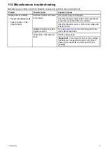
Страница 57: ...lay Check that the power source is of the correct voltage and sufficient current Software mismatch on system upgrade required Go to www raymarine com and click on support for the latest software downl...

Страница 58: ...58...

Страница 59: ...Chapter 12 Technical support Chapter contents 12 1 Raymarine product support and servicing on page 60 12 2 Checking the software version on page 61 Technical support 59...

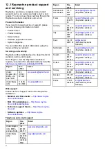
Страница 60: ...rine com manuals FAQ Knowledgebase http www rayma rine com knowledgebase Technical support forum http forum rayma rine com Software updates http www rayma rine com software Telephone and e mail suppo...

Страница 61: ...he steps below to identify the software version of your unit During normal operation 1 Press and hold the Display Power and True App buttons simultaneously for 4 seconds The software version will be d...

Страница 62: ...62...

Страница 63: ...Chapter 13 Technical specification Chapter contents 13 1 Technical specification on page 64 Technical specification 63...

Страница 64: ...urrent 45 to 65 mA Typical Display only 200 mA Maximum Transducer connected LEN Refer to SeaTalkng reference manual for further information 4 Environmental Operating temperature 20 C to 55 C Storage t...

Страница 65: ...hapter 14 Spares and accessories Chapter contents 14 1 Spares and Accessories on page 66 14 2 SeaTalkng cables and accessories on page 66 14 3 SeaTalkng cable kits on page 68 Spares and accessories 65...

Страница 66: ...2 x Backbone terminator A06031 1 x 3 m 9 8ft spur cable A06040 1 x Power cable A06049 SeaTalkng Backbone Kit A25062 Includes 2 x 5m 16 4ft Backbone cable A06036 1 x 20m 65 6ft Backbone cable A06037 4...

Страница 67: ...2 ACU SPX SeaTalkng spur cable 0 3 m 1 0 ft R12112 Connects an SPX course computer or an ACU to a SeaTalkng backbone SeaTalk 3 pin to SeaTalkng adaptor cable 0 4m 1 3ft A06047 SeaTalk to SeaTalkng spu...

Страница 68: ...connector A06064 Each connector block allows the connection of up to 3 compatible devices When correctly terminated a connector block forms a complete backbone Multiple connector blocks can be daisy c...

Страница 69: ...e A06036 2 5m 16 4ft Power cable A06049 1 1m 3 3ft Spur cable A06040 1 1m 3 3ft ACU SPX power cable R12112 for powering the SeaTalkng backbone from the autopilot system 1 0 3m 1 0ft 5 way connector A0...

Страница 70: ...er kit E22158 Parts included Quan tity Connector A Cable Connector B Length Power cable A06049 1 1m 3 3ft Backbone terminator A06031 2 N A N A N A Blanking plug A06032 N A N A N A SeaTalk 3 pin adapte...

Страница 71: ...60928 ISO Commanded address 65240 NMEA Request group function 126208 NMEA Command group function 126208 NMEA Acknowledge group function 126208 PGN list Transmit PGN s group function 126464 PGN list Re...

Страница 72: ...72...

Страница 73: ...F Fuse rating 24 L LEN See Load Equivalency Number Load equivalency number 23 Locking collar 22 M Maintenance 7 50 51 Maximum system loading 24 N Network length See Backbone length P Power connection...

Страница 74: ......

Страница 75: ......

Страница 76: ...www raymarine com Raymarine UK Limited Marine House Cartwright Drive Fareham PO15 5RJ United Kingdom Tel 44 0 1329 246 700...

Отзывы: