background image

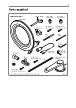
Parts supplied

D5439-4

Wheel drive parts

Clamp screw, 

M5 x 16 mm (x6)

Wheel drive

Pedestal bracket

Spoke clamp (x3)

16 mm spoke

clamp insert (x3)

12 mm spoke

clamp insert (x3)

6 mm

drill bit

3 mm

allen key

4 mm

drill bit

Power cable

4.5 m (15 ft)

Bracket screw, 

No 10 x 3/4 in (x4)

Cable clip

and screw,

No 6 x 1/2 in

Optional: Bulkhead/box pedestal fitting kit E15017 (if required)

Rudder position sensor
(if supplied)

Tiller pin

Ball joint (x2)

Stud

Nut (x2)

No 8 x ¾ inch

Countersunk head screw (x2)

No 8 x ¾ inch
Pan head screw (x3)

5

Содержание E12093

Страница 1: ...Evolution Wheel drive autopilot Installation Instructions English Date 05 2017 Document number 87287 2 2017 Raymarine UK Limited...

Страница 2: ...81131_8 book Page 118 Thursday October 7 2004 11 03 AM...

Страница 3: ...ical safety Make sure the power supply is switched off before you make any electrical connections WARNING Calibration We supply this product calibrated to default settings that should provide stable p...

Страница 4: ...onto the desired track using a navigationaid alwaysmaintainalogandmakeregularpositional plots Navigation signals can produce significant errors under some circumstances and the autopilot will not be a...

Страница 5: ...rent items of electrical equipment For optimum EMC performance it is recommended that wherever possible Raymarine equipment and cables connected to it are At least 3 ft 1 m from any equipment transmit...

Страница 6: ...81131_8 book Page 37 Thursday October 7 2004 11 03 AM...

Страница 7: ...amp insert x3 6 mm drill bit 3 mm allen key 4 mm drill bit Power cable 4 5 m 15 ft Bracket screw No 10 x 3 4 in x4 Cable clip and screw No 6 x 1 2 in Optional Bulkhead box pedestal fitting kit E15017...

Страница 8: ...0 in diameter 135 mm 5 3 in 171 mm 6 7 in plus 60 mm 2 4 in for cable clearance motor tube 48 mm 1 9 in diameter Wheel drive dimensions 28 mm 1 1 in 152 mm 6 0 in 154 mm 6 1 in 81131_8 book Page 104 T...

Страница 9: ...ing the spoke clamp holes in the front cover 2 Securing the wheel drive to the wheel 3 Attaching the pedestal bracket 4 Connecting the drive to the control unit Clamp screw M5 x 16 mm x6 Wheel drive f...

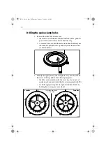
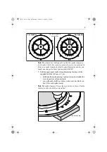
Страница 10: ...rom the drive unit as shown below 2 Identify the appropriate spoke clamp holes for your wheel With the arrow at the top refer to the following diagrams the holes are numbered inside the cover e g if y...

Страница 11: ...of the supplied drill bits 6 0 mm or 1 4 in drill from the inside placing a piece of scrap wood under the cover to produce a clean exit hole you will need to drill 4 new holes so the cover has 6 hole...

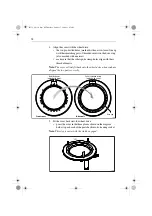
Страница 12: ...overwillonlyfitbackontothewheeldrivewhenyouhave aligned the two parts correctly 5 Fit the cover back onto the wheel drive press the cover in the three places shown on the diagram below to push each of...

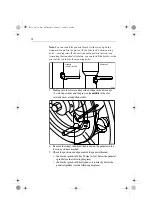
Страница 13: ...can slide the spoke clamp along the spoke to adjust its position place the insert on the spoke about 135 mm 5 3 in from the wheel center this distance is not critical as the wheel drive will self cent...

Страница 14: ...ot1installation thestandardpositionusesslot1onthebackof the wheel drive the slot closest to the motor tube so the motor tube is at the bottom to the right of the pedestal Slot 2 installation the alter...

Страница 15: ...bracket correctly 2 Measure dimension A the distance between the front of the pedestalandtherearedgeofthedrive sfrontcover seediagram you may find it easiest to hold the bracket below the wheel drive...

Страница 16: ...t the bottom of the drive unit 6 o clock position and the pin is in the middle of the slot carefully draw around the bracket 6 Remove the wheel then hold the bracket on the pedestal in the location yo...

Страница 17: ...l at right angles to the pedestal surface 10 Hold the bracket in place then lightly tighten the four cross head screws No 10 x 3 4 in As you do this make sure the bracket is correctly aligned 11 Repla...

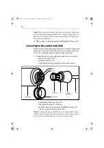
Страница 18: ...proof socket at one end 1 Connect the socket to the plug on the wheel drive s motor tube remove the socket cover pull back the plug cover align the locking ring plug and socket as shown below push the...

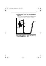
Страница 19: ...e pedestal has a cable duct use this for the drive cable to make sure that it cannot foul the steering mechanism 3 Run the drive cable back to the control unit and connect the two cores to the Drive t...

Страница 20: ...connection A B _ MOTOR POWER D13589 1 To the ACU Wheel Drive cable ACU Blue Brown NOTE You can use the autopilot control head to change the Motor phase MENU Setup Autopilot Calibration Drive Settings...

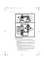
Страница 21: ...ng correct alignment CAUTION Take care to ensure correct rudder sensor alignment If the sensor is not correctly aligned the autopilot system will not perform accurately Vertical alignment When viewed...

Страница 22: ...remain parallel to each other at all times sensor arm movement must not exceed 60 if the steering system drives the sensor arm beyond these limits it will damage the rudder position sensor Maximum pe...

Страница 23: ...s rotate the sensor body then re tighten the screws Attaching the sensor to the tiller arm Attaching the tiller pin to the tiller arm 1 For optimum performance mount the tiller pin on the tiller arm 1...

Страница 24: ...gnment Move the rudder from hardover to hardover and check that at all rudder angles all moving parts of the sensor remain free from any obstructions the sensor and connecting rod remain accurately al...

Страница 25: ...our autopilot system switch on the main power breaker 2 If the control unit is active and the system operating the control unit will beep and display the pilot type Wheelor Tiller CAUTION Wheel drive...

Страница 26: ...otatingtheclutch lever clockwise so it engages fully onto the locating pip WARNING Wheel drive clutch Always reach AROUND not through the wheel to operate the wheel drive clutch lever 2 Press the 10 k...

Страница 27: ...of center If necessary bring the rudder angle to within 7 of the center by loosening the mounting bolts on the rudder position sensor rotating the base of the sensor until the reported rudder angle i...

Страница 28: ...ble autopilot control for the majority of boats You should perform the initial sea trial when you have successfully completed all of the installation functional tests and rudder sensor checks before m...

Страница 29: ...ever engages fully onto the locating pip WARNING Wheel drive clutch Always reach AROUND not through the wheel to operate the wheel drive clutch lever 3 Press auto in Auto mode the display shows the lo...

Страница 30: ...standby The display shows the boat s current compass heading 2 Disengage the autopilot to return to hand steering WheelPilot Disengagethewheeldriveclutchbyrotatingthe clutch lever anti clockwise so t...

Страница 31: ...have not corrected the compass for deviation carry out the deviation and alignment procedures Boat turns slowly and takes a long time to come onto course Rudder gain too low Boat overshoots when turn...

Страница 32: ...ol unit display shows a series of rotating dashes Compass deviation correction is running The control unit display shows a series of stationary dashes Thecontrolunitisnotreceivingdata checkthe cabling...

Страница 33: ...n the wheel drive case using mild detergent if necessary then flush thoroughly with fresh water Adjusting the clutch You need to adjust the clutch if the drive belt slips in Auto mode or drags in Stan...

Страница 34: ...ou should replace the drive belt You can obtain a replacement belt from any Raymarine dealer part number A18083 Fitting instructions are supplied with the belt User serviceable parts You can obtain th...

Страница 35: ...conditions condensation mayappearinsidethedisplay screen This will not harm the unit and you can clear it by switching on the illumination for a short time EMC advice When powered up all electrical eq...

Страница 36: ...es In general this will not damage the equipment but it can lead to spurious resetting action or momentarily may result in faulty operation 4 3 Product support Raymarine products are supported by a wo...

Страница 37: ...81131_8 book Page 76 Thursday October 7 2004 11 03 AM 35...

Страница 38: ...User notes 81176_4 fm Page 22 Tuesday April 18 2006 9 26 AM...

Страница 39: ...User notes 81176_4 fm Page 22 Tuesday April 18 2006 9 26 AM...

Страница 40: ...www raymarine com...

Отзывы: