Rudder position sensor (wheel pilot)
NOTE: Not all systems are supplied with a rudder sensor. It is
available separately as part number M81105.
The rudder position sensor connects directly to the boat’s tiller arm or
quadrant. Installing the sensor involves five main steps:
•
ensuring correct alignment
•
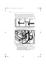
securing the sensor to the boat
•
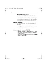
attaching the sensor to the tiller arm
•
checking alignment
•
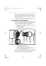
connecting to the control unit
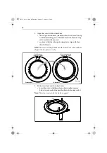
Ensuring correct alignment
CAUTION:
Take care to ensure correct rudder sensor alignment. If the
sensor is not correctly aligned, the autopilot system will not
perform accurately.
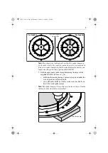
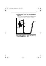
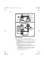
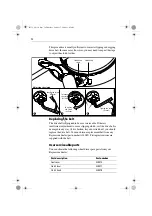
Vertical alignment
When viewed from the front (as shown in the illustration below), the
connecting rod should be as level as possible, so the ball-joints at each
end are level. It should also remain parallel to the tiller arm’s plane of
rotation at all times.
Note:
If misalignment e/-5
°
the ball-joints will bind or fail.
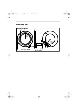
140 mm (5.5 in)
187 mm (7.35 in)
70 mm (2.75 in)
60
mm
(2.4
in)
D5386-1
81131_8.book Page 72 Thursday, October 7, 2004 11:03 AM
19
Содержание E12093
Страница 2: ...81131_8 book Page 118 Thursday October 7 2004 11 03 AM...
Страница 6: ...81131_8 book Page 37 Thursday October 7 2004 11 03 AM...
Страница 37: ...81131_8 book Page 76 Thursday October 7 2004 11 03 AM 35...
Страница 38: ...User notes 81176_4 fm Page 22 Tuesday April 18 2006 9 26 AM...
Страница 39: ...User notes 81176_4 fm Page 22 Tuesday April 18 2006 9 26 AM...
Страница 40: ...www raymarine com...

