55M4300CCE00 Rev A
5.
Accurately measure the actual radius of the suspended hook from
the centre line of slew of the machine.
6.
Use
“
”
or
“
”
to adjust the Corr.:
x.x
value until the displayed
radius equals the measured radius, note that the indicated radius should
normally be increased, not decreased. Press
“
”
to accept, the display will
change to show:
7.
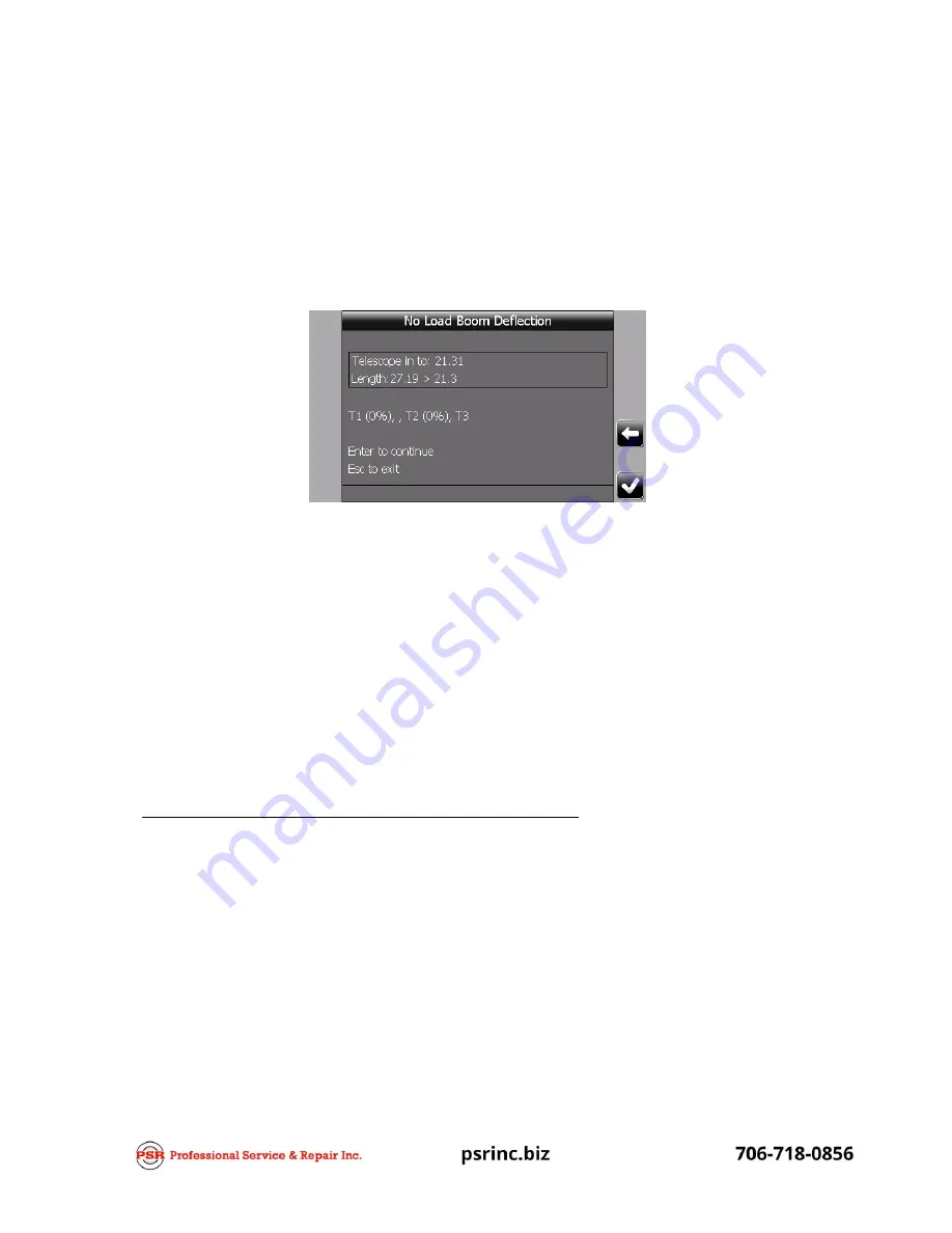
Telescope in to between 1/3
rd
and ½ of the extension range being
calibrated, remember to ignore the target value if working with multi-reel or
dual telescoping mode booms.
8.
When the boom is at the desired extension, press
“
”
to accept,
the display will change to show the current boom angle followed by a target
boom angle for calibration.
9.
Accurately measure the actual radius of the suspended hook and
adjust the new correction value until the displayed radius equals the measured
radius. Press
“
”
to accept.
10.
Press
“
”
to return to the main calibration menu.
Step #15: Main boom “Loaded boom deflection”
This procedure is used to add an allowance into the calculation of the hook radius to
compensate for main boom and/or chassis deflection due to a suspended load. A
separate calibration is available for each crane configuration that also has an individual
no load calibration, but is not used for configurations with boom attachments (refer to
Section 3.10).
A no load calibration should be completed before continuing with this procedure.
This procedure should only be used with machine configurations on outriggers or on
crawlers.
A known test weight is required to carry out this calibration, the weight should be
between 50% and 90% of the SWL for the configuration being calibrated and should be
based on the SWL with a fully extended boom at approximately 60° boom angle. The


