Place the cooker in the intended position and out lift the surface
ground hotplate, checking that the joint between the underside
of the hob and the top of the cooker is intact.
Any joints which have opened should be made good with fire
cement provided.
If the appliance is installed near combustible material then as
well as adhering to minimum clearances in Fig. 1 additional
non-combustible insulation must be fitted to the wall to protect
the area around the flue and fluebox. The insulation must reach
a minimum distance of 150mm either side of the flue/flue box
and follow the line of the flue. The minimum specification for
this material is Superwool 607 LTI with a density of 320kg/m3,
a thickness of 10mm and a self finish. There must be a
minimum 16mm air gap between the insulation board and an
adjacent combustible wall surface. A higher specification
material may be used but the air gap must be maintained
.
Check that the boiler/cooker flueway dampers operate correctly
by turning the knob on the front plate adjacent to the top left
hand corner of the roasting oven door.
NOTE: IT IS NOT VISUALLY POSSIBLE TO SEE THE
BOILER DAMPER AND THIS SHOULD BE CHECKED BY
FEELING THROUGH THE HOTPLATE APERTURE TO THE
BACK OF THE COOKER. THE COOKER DAMPER SPINDLE
OPERATES THE BOILER DAMPER WHICH CAN BE FELT
BY INSERTING HAND INTO FLUEWAY.
Replace the hotplate making sure that it is seating evenly on
the soft rope and that it is approximately 1.5mm proud of the
enamelled top plate, with an equal space all round.
1. Connect pipework to boiler flow and return tappings.
2. Fit the flue chamber which should have a rope seal already
installed. The flue chamber is screwed to the cooker making
a good seal as any air leak at this point will impede the
working of the cooker.
3. Open the firebox and ashpit doors and check that the
reciprocating bottomgrate bars are in position. Operate the
riddling lever to ensure bottomgrate operation.
4. Turn the boiler thermostat knob at the rear left hand corner
of the top plate from No.1 (low) to No.8 (high).
NOTE: THE HIGHER THE NUMBER, THE HIGHER THE
WATER TEMPERATURE.
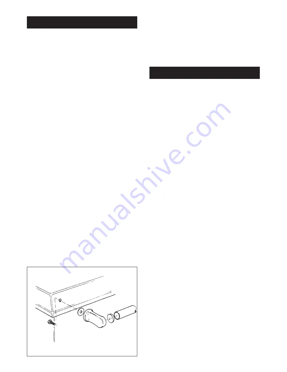
The handrail brackets are held on the front ends of the cooker
top-plate casting. Remove the travel nuts and replace with the
handrail brackets ensuring the fibre protecting washers are in
position. Insert the handrails with fitted endcaps into the
brackets, positioning them correctly, and tighten the locating
bolts (Fig. 9).
After completing the installation, the Heating Contractor should
demonstrate to the user, the operation of the appliance and the
routine cleaning method.
Check that the system is full of water and free from air locks.
When lighting pull the flue chamber damper open to maximum,
add paper and sticks with a small quantity of fuel through
fuelling aperture onto bottomgrate and close the firebox door.
Open ashpit door, ignite fuel and close ashpit door when fuel is
well alight with boiler thermostat knob or spinwheel on ashpit
door at required setting.
Allow the cooker to heat up gradually at first time lighting.
NOTE: SMOKE/SMELL EMITTED DURING INITIAL USAGE
Some parts of the cooker have been coated with a light
covering of protective oil. During initial operation of the cooker,
this may cause smoke/smell to be emitted and is normal and
not a fault with the appliance, it is therefore advisable to open
doors and or windows to allow for ventilation. Lift the lids to
prevent staining the linings.
7
TESTING AND COMMISSIONING
INSTALLATION
DESN 510454 A
Fig. 9


