M7 GX Technical Manual
8
Raveon Technologies Corp.
8. Setup and Initial Configuration
1.
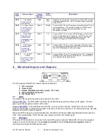
Connect a DC power source to the DC IN connection on the front of the modem.
2.
Connect a good quality antenna, cut to the operating frequency, to the BNC connector on the front of
the modem.
3.
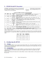
Connect a computer terminal, or PC computer running HyperTerminal, to the 9-pin I/O connector. The
factory default serial ports settings are 4800 bps, 8 data bits, 1 stop, no parity.
4.
Put the
M7 GX
into the command mode. (enter
+++
per Section 0)
5.
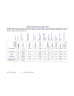
Program the GPS mode. See the table on
Page 4
to identify the mode to use, and set it with the
GPS x
command. Type
GX
and press enter to see an overview of the current GPS related features and
configuration. For in-vehicle transponders that do not connect to PCs or displays, it is usually
GPS 1
mode. For M7’s connected to a PC running RavTrack PC software, it is set to
GPS 2.
6.
Program the modem’s operating frequency to your desired operating frequency. This is done with the
ATFX xxx.xxxxx
command.
7.
Program the ID in the unit. Sequentially number the M7 GX units in your system, starting with 1. Use
the
ATMY
command to set the ID.
8.
Program the ID to which this unit will send its data to. Typically this is the ID of the “Base” unit.
9.
Program the
SLOTNUM.
This is the TDMA slot number that this unit will transmit in. By default it is the
same as its ID
.
Important!
All radios in your system must use different SLOTNUM settings
.
10.
ATMK
The network address mask. Default is F000. This means this unit will receive all
transmissions from any other unit with an ID beginning with 0 (0001 thru 0999).
11.
KEYPHRASE
Enter a security key code “keyphrase”. Use any word or phrase 1-16 characters
long. It is case-sensitive. DO NOT FORGET WHAT YOU SET IT TO! The KEYPHRASE is the only
parameter that cannot be read out of the M7 GX. It must be the same as the KEYPHRASE
programmed into all the other M7 GX transponders in your system. The factory default KEYPHRASE
is RAVEON, call capitols.
12.
To see an overview of how the modem is configured, use the
SHOW
command. To see an overview
of how the GPS features are configured, use the
GX
command.
13.
Verify the
SLOTTIME
and
TDMATIME
are set appropriate for your system. Consult the user manual if
you are not sure. The defaults are 200mS SLOTTIME and 10 second TDMATIME, which will give you
50 slots (numbered 0-49) to track 49 transponders.
14.
Once the unit is configured, type
EXIT
to exit the command mode.
Remember, that from the factory, all
M7
GX GPS transponders are configured to simply work. Plug in power
and they will lock onto the GPS satellite signal and begin transmitting their positions and status in their
appropriate time slot.
8.1.
Enabling Repeater Features
Refer to the technical manual for advanced repeater configuration instructions. To quickly enable repeating
of all data sent from/to units 1-999, use the
REPEAT 1
command. This will enable the repeater function, and
configure it to repeat messages, position, and status transmissions.
8.2. Set the Transmission Report rate
Use the
TXRATE xx
command to set the report rate, in seconds, for the
M7 GX
transponder. For example,
if you wish the M7 to report every 5 minutes, set the report rate to 300 seconds (
TXRATE 300
).
If the
M7 GX
should report position and status when it is moving, set the
TXRATE xx
to the desired time
between position transmissions. Then, program the
IDLERATE xx
to the desired number of seconds
between reports when the unit is not moving (idle).
Important!:
Set the minimum distance the unit must move for a transmission occur with the
TRIGDX xx
command. If
TRIGDX
is set to zero, then the unit will always report at the interval set with the
TXRATE xx
command. This is the factory default setting.
For example, to transmit every 2 minutes when idle, and every 10 seconds when moving more than 500
meters, use these commands:
IDLERATE 120
(
to set the idling update interval to 2 minutes.)


