background image

8

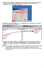
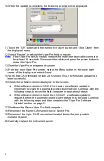
10.When the update is complete, the following prompt will be displayed.

11.Touch the “OK” button and then select the “Start” button and “Shut Down” from 

the displayed menu.

12.Select “Restart” to reboot the Viper Pro field computer.

Note:  

If the Viper Pro fails to restart, remove the main interface cable connector 
for at least 10 seconds. Reconnect the cable and press the power button to 
restart the Viper Pro.

13.Start the Viper Pro management system.

14.From the main Viper Pro screen, select the Menu button in the lower, right 

corner of the display and select About.

15.Verify that CAN firmware version 22 is shown. If so, the firmware update has 

been successful.

16.Check the software version displayed on the screen.

a.

If the software version is 3.5.0.21 or newer, no software update is 
necessary to utilize the automatic power down feature. Continue with the 
following steps to return the field computer to operational status.

b.

If the software version is lower than 3.5.0.21, a software update is 
required before the automatic power down feature may be used. Continue 
with the following steps and then complete the “Viper Pro Software 
Update” section on page 9.

17.Shutdown the Raven Viper Pro field computer.

18.Reconnect the Raven CAN switch box or Switch Pro.

19.Reconnect the 4-pin ‘CAN’ connectors located below the pump switch 

instrument panel.

20.Carefully replace the instrument panel.

Содержание Viper Pro

Страница 1: ...for Raven Viper Pro Field Update Guide...

Страница 2: ...dustries for update Contact a local Raven dealer for assistance Important Safety Information Read the following procedures carefully before installing the field update kit and follow all safety inform...

Страница 3: ...Pro to prevent damage to the field computer 3 Locate the instrument panel with the product pump and hydraulic shut off switch in the vehicle cabin Remove the 4 screws and carefully lift the instrument...

Страница 4: ...ring the field computer approximately 2 in 5 cm from the factory splice Note A crimp connector will be installed on the red power wire still connected to the factory splice later in this process 7 Loc...

Страница 5: ...st located in the right rear corner below the cabin 11 Open the panel on the front side of the console along the right side of the vehicle cabin 12 Locate the grey wire with the female 1 4 quick disco...

Страница 6: ...ed to take advantage of the automatic power down feature on the field computer Review the following procedure to complete the installation of the field update kit 1 Locate the round 16 pin cable conne...

Страница 7: ...onnector labeled CAN under the pump switch instrument panel The connector should be located near the factory power and ground cluster found earlier in the field update process 2 Disconnect the 4 pin c...

Страница 8: ...e disk contents 9 Double click on the ViperST10 Programmer exe icon to begin the update process The update may take approximately 15 seconds to begin When the update is in progress the Viper Pro will...

Страница 9: ...version 22 is shown If so the firmware update has been successful 16 Check the software version displayed on the screen a If the software version is 3 5 0 21 or newer no software update is necessary t...

Страница 10: ...web site 1 Insert the provided USB flash drive P N 063 0173 427 into the Viper Pro 2 Press the power button on the Viper Pro field computer 3 Touch the Display Program List button when the following...

Страница 11: ......

Страница 12: ...x Falls SD 57117 5107 Fax 605 331 0426 www ravenprecision com www ravenhelp com Notice This document and the information provided are the property of Raven Industries Inc and may only be used as autho...

Отзывы: