3
Manual No. 016-0171-148
23
Installation
AccuBoom™
Refer to the machine specific installation materials for instructions on installing AccuBoom on the machine.
Note:
When used with a CAN product control system, AccuBoom requires a boom/speed node with
program D or newer for proper AccuBoom functionality.
AccuBoom™ Master Switch
The AccuBoom master switch option will allow AccuBoom to toggle coverage mapping and section information
as reported by the AccuBoom node.
To enable the AccuBoom master switch, connect the orange wire with white stripe on the AccuBoom node
harness to the machine master switch. Contact a local Raven dealer for more information on part numbers and
availability of the AccuBoom feature for the specific sprayer model.
Contact the machine’s manufacturer for more information on connecting this feature.
Lightbar
Envizio Pro and Envizio Pro II field computers are capable of interfacing with an external Raven lightbar
through the auxiliary interface cable (P/N 115-0171-745) or the chassis interface cable (P/N 115-0171-926).
If an external lightbar is desired, follow the installation instructions provided with the lightbar before connecting
the lightbar to the field computer. Once installation of the lightbar is complete, connect the lightbar cable to the
serial connector labeled ‘COM 3’ on the appropriate interface cable. See Chapter 7,
, for
information on configuring the field computer to send messages to the external lightbar.
TM-1 Tilt Module
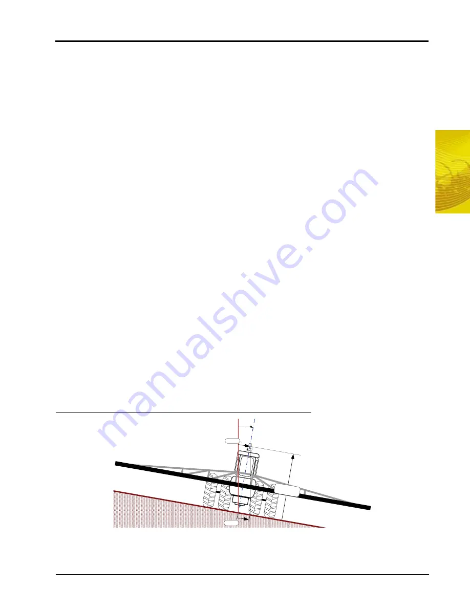
GPS receivers output position information relative to the position of the DGPS antenna. Most often, the
antenna is mounted on the top of the machine which means the GPS location is only accurate when the
machine is on level ground. On uneven terrain, such as side hills, the actual ground position may differ from
the location of the GPS antenna.
FIGURE 10.
Reported GPS Position Error Due to Side Hill
The Raven TM-1 Tilt Module compensates for any tilt of the vehicle from a level field condition. To supply tilt
compensated GPS signal, the Raven TM-1 Tilt Sensor receives a raw DGPS signal from the DGPS receiver
and outputs a tilt corrected signal to guidance devices or controllers.
Antenna
Height
Tilt
Angle
ST ARLI NK
Error
Error
Содержание Envizio Pro
Страница 1: ...Software Version 3 2 Envizio Pro Envizio Pro II Installation Operation Manual...
Страница 36: ...Chapter 3 26 Envizio Pro and Envizio Pro II Installation and Operation Manual...
Страница 148: ...Chapter 7 138 Envizio Pro and Envizio Pro II Installation and Operation Manual...
Страница 158: ...Chapter 8 148 Envizio Pro and Envizio Pro II Installation and Operation Manual...
Страница 174: ...Chapter 9 164 Envizio Pro and Envizio Pro II Installation and Operation Manual...
Страница 178: ...Chapter 10 168 Envizio Pro and Envizio Pro II Installation and Operation Manual...
Страница 184: ...Chapter 11 174 Envizio Pro and Envizio Pro II Installation and Operation Manual...
Страница 210: ...Appendix D 200 Envizio Pro and Envizio Pro II Installation and Operation Manual...
Страница 230: ...Index 220 Envizio Pro Envizio Pro II Installation Operation Manual...


