background image


Instruction manual


RAVAGLIOLI S.p.A. 


RAVTD1760 WS – RAVTD1780 WS 


Code M0197  - rev.1.0

(11/2010)


RAVAGLIOLI S.p.A. - 

Via I° Maggio, n° 3 (Pontecchio Marconi) 


40037 Sasso Marconi (Bologna - Italy) 


Tel. 051/ 67.81.511 – Fax 051/ 84.64.67 E-mail: [email protected] 


COMPOSIZIONE COMPOSITION ZUSAMMENSETZUNG COMPOSITION 

COMPOSICIÓN 

54 pagine (copertine 
comprese) 

54 pages (including 
cover pages) 

54 Seiten (inkl. 
Deckblätter) 

54 pages (pages de la 
couverture incluses) 

54 páginas (incluidas 
las portadas) 

52 pagine numerate 

52 numbered pages 

52 numerierte Seiten 

52 pages numérotées 

52 páginas numeradas 


• Per eventuali chiarimenti interpellare il più vicino rivenditore oppure rivolgersi direttamente a: 
• For any further information please contact your local dealer or call: 
• Im Zweifelsfall ober bei Rückfragen wenden Sie sich bitte an den nächsten Wiederverkäufer oder direkt an: 
• Pour tout renseignement complémentaire s’adresser au revendeur le plus proche ou directement à: 
• En caso de dudas, para eventuales aclaraciones, póngase en contacto con el distribuidor más próximo ó 

diríjase directamente a: 


RAVTD1760 WS – RAVTD1780 WS 


MANUALE DI ISTRUZIONE 

INSTRUCTION MANUAL 

BETRIEBSANLEITUNG 

MANUEL D’INSTRUCTIONS 

MANUAL DE INSTRUCCIONES


Содержание RAVTD1760 WS

Страница 1: ...ered pages 52 numerierte Seiten 52 pages num rot es 52 p ginas numeradas Per eventuali chiarimenti interpellare il pi vicino rivenditore oppure rivolgersi direttamente a For any further information pl...

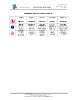
Страница 2: ...DEN VERBOTEN INTERDIT PROHIBIDO Obbligo Operazioni o interventi da eseguire obbligatoriamente Mandatory Operations or jobs to be performed compulsorily Vorschirift Obligatorisch auszuf hrende Arbeitsv...

Страница 3: ...A35 11 3 7 4 Clamps STDA46 11 3 8 Rotating Plates 12 3 8 1 Rotating Plates S110A7 12 3 8 2 Electronic Rotating Plates Connected to Detectors with STDS43 Via Radio Transmission 12 4 SWITCHING THE MACHI...

Страница 4: ...ions Menu 38 8 14 Printout of Measurements taken 39 9 DATABASE CUSTOMISATION 42 9 1 New Group Entry 42 9 2 New Group Deletion 43 9 3 New Vehicle Entry 44 9 4 Customised Vehicle Deletion 47 10 PROGRAMM...

Страница 5: ...er cable This product features a 3 wire plug with built in grounding It can be plugged into a socket with built in grounding only Should a grounded socket not be available for machine connection conta...

Страница 6: ...r to the instruction manual and then if such doubts persist contact an authorised after sales centre or RAVAGLIOLI S p A technical assistance directly 2 1 General Preventive Measures During operation...

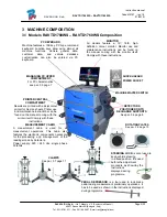
Страница 7: ...All models feature a 19 16 9 high definition colour monitor Monitor use and maintenance instructions can be found on the manual coming with the monitor itself Comply with these instructions PRINTER CE...

Страница 8: ...acy Accuracy Axle Measurement Measurement Range Measurement Total Range Toe 2 2 20 x 2 Partial toe 1 1 20 Set back 2 2 5 Camber 2 3 10 Caster 5 10 18 Front Kingpin 5 10 18 Toe 2 2 20 x 2 Partial toe 1...

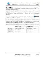
Страница 9: ...g infrared detectors is effective also under critical lighting conditions Data are transmitted from front detectors VIA RADIO through modules located inside front detectors and cabin Rear detectors do...

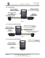
Страница 10: ...KEYPAD see par 3 6 4 on page 10 BATTERY COMPARTMENT GREEN LED indicating that detector is under charge RED LED indicating that detector is on DETECTOR PIN LOCKING KNOB LED for tolerance indication see...

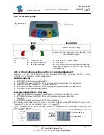
Страница 11: ...and for tolerance during adjustment Levelling indicator RED LED on detector is not levelled RED LED flashing and GREEN LED steady on detector is close but not levelled GREEN LED ONLY is flashing detec...

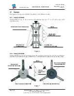
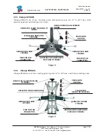
Страница 12: ...TDA33 are of the screw on self centering type for 10 to 19 alloy rims with removable tabs Figure 6 3 7 2 Clamps STDA34 Clamps STDA34 are of the 3 resting point self centering type for 10 to 19 rims an...

Страница 13: ...e 8 3 7 4 Clamps STDA46 Clamps STDA46 are of the 4 resting point type for 10 to 20 rims and feature locking units Figure 9 HANDLES FOR CLAMP QUICK COUPLING TO WHEEL KNOBS FOR CLAMP COUPLING TO WHEEL K...

Страница 14: ...r of 250 mm and a loading capacity of 1 000 kg Figure 10 3 8 2 Electronic Rotating Plates Connected to Detectors with STDS43 Via Radio Transmission Electronic rotating plates STDA43 have a 300 mm anti...

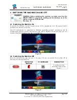
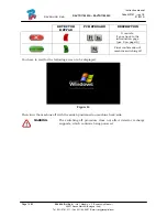
Страница 15: ...See chap 10 4 1 Switching the Machine On To switch the machine on and to gain access to the programme turn the special switch positioned on machine back side Once PC initialisation is completed by Wi...

Страница 16: ...mail rav ravaglioli com DETECTOR KEYPAD PC KEYBOARD DESCRIPTION It cancels It goes back to the introduction page par 8 on page19 Final confirmation of machine switching off You have to wait for the f...

Страница 17: ...ex cabin is off It is anyway recommended to always switch detectors manually off see par 3 6 4 on page 9 when they are not used 6 FLAT BATTERY INDICATION System displays a flat battery warning signal...

Страница 18: ...n the machine parts type make a Bluetooth search to couple detectors with cabin Print Menu Print can be customised by entering workshop data selecting the type of desired printout and selecting the pr...

Страница 19: ...Select GROUPS CONFIGURATION from programme configuration page as explained in par 7 on page 16 You can edit system parameters database profile and specify which parts are fitted on the machine and pa...

Страница 20: ...profiles It moves selection up displaying the following profiles It confirms selection Page Figure 18 displays a list with the different DATABASE profiles including the MAKES of the vehicles circulati...

Страница 21: ...ction Page Upon machine switching on see par 4 1 on page13 programme start screen will be displayed You can select different functions Figure 21 DETECTOR KEYPAD PC KEYBOARD DESCRIPTION It switches mac...

Страница 22: ...23 Note by pressing F5 you select the search mode Through search keys such as Make name model year or VIN Figure 23 or through a manual selection Figure 24 Figure 23 Press to move cursor from model na...

Страница 23: ...lsorily selected DETECTOR KEYPAD PC KEYBOARD DESCRIPTION It goes back to the introduction page par 8 1 on page19 It moves selection up It moves selection down It confirms selection and goes to the fol...

Страница 24: ...age 19 a screen showing the measurements and tolerances supplied by the manufacturer is displayed Figure 25 DETECTOR KEYPAD PC KEYBOARD DESCRIPTION It goes back to vehicle selection par 8 2 on page 19...

Страница 25: ...the values specified by the manufacturer Position and distribute any load envisaged by the manufacturer 8 4 2 Run Out Preparation After having displayed vehicle technical specification page see par 8...

Страница 26: ...ons par 8 4 2 on page23 Make measurement preliminary operations par 8 6 on page 32 It is recommended to thoroughly comply with the displayed instructions During the start phase the central keys of the...

Страница 27: ...irst target is to turn wheel by 120 and reach the first highlighted point Rotation can be made in both directions but it is nevertheless recommended to follow the direction shown by the arrow to reach...

Страница 28: ...acquisition programme will automatically continue and the following screen will be displayed Figure 32 On Figure 32 the front left wheel is shown with a tick on the side to indicate that the procedur...

Страница 29: ...e turned twice by 180 instead of being turned three times by 120 as described above 8 5 2 Thrust Run Out with Automatic Acquisition To carry out the thrust Run Out with automatic acquisition procedure...

Страница 30: ...the following screen will be displayed Figure 35 Move vehicle forward again until the rotation of the wheel did not make back 30 degrees forward final point STOP will be displayed for approx three se...

Страница 31: ...Run Out inclinometer Lower the reference detector usually it is the left front one until its end is almost touching the ground then lock it in place RELEASE the other detectors so that they are free t...

Страница 32: ...ax 051 84 64 67 E mail rav ravaglioli com Figure 39 STOP is displayed for approx three seconds which is enough for the programme to acquire measurement readings Figure 40 Position reference sensor aga...

Страница 33: ...velled and when finished press central key to confirm STOP is displayed for approx three seconds which is enough for the programme to acquire measurement readings Figure 43 The thrust Run Out procedur...

Страница 34: ...page 24 It continues to the alignment procedure par 8 7 on page 33 1 Lower vehicle so as to make wheels rest on lift platforms of course only if the Run Out procedure has been carried out with raised...

Страница 35: ...ashing based on detectors levelling If front wheels are too misaligned no levelling will be displayed NOTE Once detector alignment and levelling operations are completed the STOP images will be displa...

Страница 36: ...ent and levelling procedure par 8 7 on page 33 Press this key to select the type of steering to be made It displays vehicle diagnosis page par 8 9 on page 35 Type of steering to be made Steering at 20...

Страница 37: ...KEYPAD PC KEYBOARD DESCRIPTION Repeat steering procedure par 8 8 on page34 It changes values displaying layout It displays vehicle technical specifications it may be changed if needed par 8 3 on page...

Страница 38: ...djustment Rear axle adjustment procedure can be made by pressing F4 from Figure 50 after having carried out adjustment preliminary operations par 8 10 on page 36 Proceed to adjustment where allowed as...

Страница 39: ...2 to display a menu page with additional functions par 8 13 on page 38 Now select Caster Adjustment Once caster values have been adjusted or even if they are not adjusted as they are deemed to be corr...

Страница 40: ...RELIMINARY OPERATIONS see par 8 4 1 on page 23 TOE CURVE Toe curve can be adjusted by following the displayed figures as follows Settle vehicle press F4 Position the special tool under front axle pres...

Страница 41: ...selecting the following key from the customer data entry page the following screen will be displayed Figure 54 DETECTOR KEYPAD PC KEYBOARD DESCRIPTION Repeat steering procedure par 8 8 on page 34 It...

Страница 42: ...highlight them A report on the performed test is printed with customer data vehicle data before and after adjustment vehicle technical specifications supplied by manufacturer and any other remarks fo...

Страница 43: ...TD1760 WS RAVTD1780 WS Code M0197 rev 1 0 11 2010 RAVAGLIOLI S p A Via I Maggio n 3 Pontecchio Marconi Page 41 52 40037 Sasso Marconi Bologna Italy Tel 051 67 81 511 Fax 051 84 64 67 E mail rav ravagl...

Страница 44: ...icles 9 1 New Group Entry To create customised groups and store them inside database the group configuration page shall be displayed see par 7 1 on page 17 Press Ins on the keyboard The following scre...

Страница 45: ...letion You have to display the group configuration see par 7 1 on page 17 select the customised group you want to delete then press cancel and press F4 to confirm Figure 60 Warning If a customised gro...

Страница 46: ...highlighted point the make of the selected vehicle is highlighted by a red background You can enter or confirm the name of the make of the vehicle you want to create Then select and enter Vehicle mod...

Страница 47: ...45 52 40037 Sasso Marconi Bologna Italy Tel 051 67 81 511 Fax 051 84 64 67 E mail rav ravaglioli com Figure 62 After having selected rim diameter the following data to be entered are vehicle track an...

Страница 48: ...um refers to can be adjusted or not The point to which the data refer can be adjusted To define it as not adjustable press The point to which the data refer cannot be adjusted To define it as adjustab...

Страница 49: ...can observe that also the just created customised vehicle is present it is listed under a separate make in alphabetical order written in italic Using the same procedure you can edit the values of a c...

Страница 50: ...e DATABASE Figure 66 Every machine has its own unique SMARTCARD that cannot be replaced with the SMARTCARD of another machine for whatever reason Should this SMARTCARD be removed or replaced programme...

Страница 51: ...as an alternative to the communication of customer s SMARTCARD serial number F4 It allows copying the correct path of the DATABASE file that has been previously downloaded from internet and inserted...

Страница 52: ...and rear detectors Rear detectors do not directly communicate with cabin their data are transmitted received passing through front detectors so if a front detector is not working properly data could...

Страница 53: ...l and by the use of non original spare parts Before doing any operation on the system always disconnect the power supply In case of doubt do not interpret but contact RAVAGLIOLI S p A technical assist...

Страница 54: ...a potential hazard risk must be correctly disposed of Dispose of parts according to category Scrap as iron scrap through authorised channels Parts considered as special waste must be removed and spli...

Отзывы: