background image

Machine settings

69

8

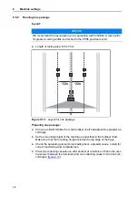
Figure 8.7:

Spreading vane adjustment; example spreading vane M1, position 
B2

A to E: Length adjustment
1 to 6: Angle adjustment

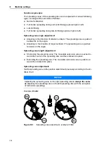
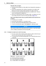
Figure 8.8:

Spreading vane adjustment; example spreading vane M1X, posi-
tion X3

X: Fixed length adjustment
1 to 6: Angle adjustment

Structure of spreading disc M1X: see 

12.11: Replacing the MDS-spreading vane 

with an X-spreading vane, page 132

.

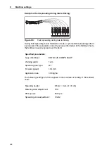
ENTEC

R

26 COMPO BASF

26%N + 13%S, 0,96 kg / l

g

n

u

g

n

d

l

a

m

r

o

N

10 m

12 m

15 m

16 m

18 m

M1

M1

M1

M1

M1

450

540

540

540

600

40 / 40

50 / 50

60 / 60

60 / 60

70 / 70

C 3 -

C 3 - B 2

D 4 - B 2

D 4 - B 2

E 4 - B 2

A 3 - A 3

A 3 - A 3

A 4 - A 4

A 4 - A 4

A 4 - A 4

B

1.0

kg / ha

km/h

km/h

km/h

km/h

km/h

8

10

12

8

10

12

8

10

12

8

10

12

8

10

12

60

20,8

156

124

104

70

24,6

184

147

123

153

123

102

80

28,4

213

170

142

177

142

118

90

32,2

241

193

161

201

161

134

161

128

107

150

120

100

100

36,0

270

216

180

225

180

150

180

144

120

168

135

112

150

120

100

110

40,0

300

240

200

250

200

166

200

160

133

187

150

125

166

133

111

120

44,0

330

264

220

275

220

183

220

176

146

206

165

137

183

146

122

130

48,0

360

288

240

300

240

200

240

192

160

225

180

150

200

160

133

140

52,0

390

312

260

325

260

216

260

208

173

243

195

162

216

173

144

150

56,0

420

336

280

350

280

233

280

224

186

262

210

175

233

186

155

160

60,0

450

360

300

375

300

250

300

240

200

281

225

187

250

200

166

170

64,0

480

384

320

400

320

266

320

256

213

300

240

200

266

213

177

180

68,0

510

408

340

425

340

283

340

272

226

318

255

212

283

226

188

190

72,0

540

432

360

450

360

300

360

288

240

337

270

225

300

240

200

200

76,0

570

456

380

475

380

316

380

304

253

356

285

237

316

253

211

210

79,8

598

478

399

498

399

332

399

319

266

374

299

249

332

266

221

220

83,6

627

501

418

522

418

348

418

334

278

392

313

261

348

278

232

230

87,4

656

524

437

546

437

364

437

349

291

410

328

273

364

291

243

240

91,3

684

547

456

570

456

380

456

365

304

428

342

285

380

304

253

250

95,1

713

570

475

594

475

396

475

380

317

446

356

297

396

317

264

260

98,9

742

593

494

618

494

412

494

395

329

463

371

309

412

329

274

270

102

771

616

514

642

514

428

514

411

342

481

385

321

428

342

285

280

106

799

639

533

666

533

444

533

426

355

499

399

333

444

355

296

290

110

828

662

552

690

552

460

552

441

368

517

414

345

460

368

306

300

114

857

685

571

714

571

476

571

457

381

535

428

357

476

381

317

310

117

884

707

589

736

589

491

589

471

392

552

442

368

491

392

327

320

121

910

728

607

759

607

506

607

485

404

569

455

379

506

404

337

330

125

937

750

625

781

625

520

625

500

416

585

468

390

520

416

347

340

128

964

771

642

803

642

535

642

514

428

602

482

401

535

428

357

350

132

991

792

660

825

660

550

660

528

440

619

495

412

550

440

367

360

135

1017

814

678

848

678

565

678

542

452

636

508

424

565

452

377

370

139

1044

835

696

870

696

580

696

557

464

652

522

435

580

464

386

380

142

892

714

595

714

571

476

669

535

446

595

476

396

390

146

915

732

610

732

585

488

686

549

457

610

488

406

400

150

937

750

625

750

600

500

703

562

468

625

500

416

410

154

962

770

641

770

616

513

721

577

481

641

513

427

420

158

987

790

658

790

632

526

740

592

493

658

526

438

430

162

1012

810

675

810

648

540

759

607

506

675

540

450

440

166

1037

830

691

830

664

553

778

622

518

691

553

461

450

170

850

680

566

796

637

531

708

566

472

460

174

870

696

580

815

652

543

725

580

483

MDS 10.1 / 11.1 / 12.1

17.1 / 19.1

B 2

B 2

Piagran SKW Piesteritz

46%N, 0,77 kg / l

Normald ¨ungung

20 m

21 m

24 m

M1X

M1X

M1X

540

540

540

50 / 50

50 / 50

70 / 70

X 3

- C 3

X 3 - D 3

X 4 - D 3

X 2 - C 4

X 2 - C 4

X 3 - C 4

B

0.6

kg / ha

km/h

km/h

km/h

8

10

12

8

10

12

8

10

12

100

23,4

87,7

70,2

58,5

83,5

66,8

55,7

110

26,0

97,5

78,0

65,0

92,8

74,2

61,9

81,2

65,0

54,1

120

28,5

107

85,8

71,5

102

81,7

68,0

89,3

71,5

59,5

130

31,2

117

93,6

78,0

111

89,1

74,2

97,5

78,0

65,0

140

33,8

126

101

84,5

120

96,5

80,4

105

84,5

70,4

150

36,4

136

109

91,0

130

104

86,6

113

91,0

75,8

160

39,0

146

117

97,5

139

111

92,8

121

97,5

81,2

170

41,5

155

124

103

148

118

99,0

129

103

86,6

180

44,2

165

132

110

157

126

105

138

110

92,0

190

46,8

175

140

117

167

133

111

146

117

97,5

200

49,4

185

148

123

176

141

117

154

123

102

210

52,4

196

157

131

187

149

124

163

131

109

220

55,4

207

166

138

198

158

132

173

138

115

230

58,4

219

175

146

208

167

139

182

146

121

240

61,4

230

184

153

219

175

146

192

153

128

250

64,5

241

193

161

230

184

153

201

161

134

260

67,5

253

202

168

241

192

160

211

168

140

270

70,5

264

211

176

251

201

167

220

176

146

280

73,5

275

220

183

262

210

175

229

183

153

290

76,5

287

229

191

273

218

182

239

191

159

300

79,6

298

238

199

284

227

189

248

199

165

310

82,9

311

248

207

296

237

197

259

207

172

320

86,3

323

259

215

308

246

205

269

215

179

330

89,7

336

269

224

320

256

213

280

224

187

340

93,1

349

279

232

332

266

221

291

232

194

350

96,5

362

289

241

344

275

229

301

241

201

360

99,9

374

299

249

356

285

237

312

249

208

370

103

387

309

258

369

295

246

322

258

215

380

106

400

320

266

381

304

254

333

266

222

390

110

412

330

275

393

314

262

344

275

229

400

113

425

340

283

405

324

270

354

283

236

410

116

436

348

290

415

332

276

363

290

242

420

119

446

357

297

425

340

283

372

297

248

430

121

457

365

304

435

348

290

381

304

254

440

124

468

374

312

445

356

297

390

312

260

450

127

478

382

319

455

364

303

398

319

265

460

130

489

391

326

466

372

310

407

326

271

470

133

499

399

333

476

380

317

416

333

277

480

136

510

408

340

486

388

324

425

340

283

490

138

521

416

347

496

397

330

434

347

289

500

141

531

425

354

506

405

337

443

354

295

MDS 10.1 / 11.1 / 12.1

17.1 / 19.1

X 3

Содержание MDS 14.2

Страница 1: ...ture reference This instruction manual assembly instruc tion is to be considered as part of the ma chine Suppliers of new and second hand machines are required to document in wri ting that the instruc...

Страница 2: ...included in your machine Please note that damage caused by incorrect operation or improper use is not covered by war ranty claims Technical improvements We are continuously improving our products The...

Страница 3: ...1 Parking the machine 8 3 5 2 Filling the machine 8 3 5 3 Checks before start up 9 3 5 4 Hazard zone 9 3 5 5 Operation 10 3 6 Use of fertiliser 10 3 7 Hydraulic system 10 3 8 Maintenance and repair 11...

Страница 4: ...4 14 Practice test kit PPS5 31 4 4 15 Fertiliser identification system DIS 31 5 Axle load calculation 33 6 Transportation without tractor 37 6 1 General safety instructions 37 6 2 Loading and unloadi...

Страница 5: ...eading unit GSE 7 optional equipment 79 8 7 3 Limited or full border spreading with the limited border spreading unit TELIMAT T1 optional equipment 79 8 8 Spreading small strips of field 79 9 Calibrat...

Страница 6: ...wear 121 12 7 Checking the spreading disc hub 121 12 8 Removing and mounting spreading discs 122 12 8 1 Removing the spreading discs 122 12 8 2 Mounting the spreading discs 122 12 9 Checking the agita...

Страница 7: ...The notes on the operation service and secure handling of the machine as de scribed in this operating manual and in the form of warning notes and pictorial warnings at the machine issued by the manufa...

Страница 8: ...Intended use 1 2...

Страница 9: ...ew owner The operator s manual is intended for the operator of the machine and anyone involved in operating and maintaining it It must be read understood and applied by all persons entrusted with the...

Страница 10: ...ront of these instructions Handling instruction 2 3 2 Listings Listings without a specific sequence are shown with bullet points level 1 and dashes level 2 Property A Point A Point B Property B 2 3 3...

Страница 11: ...omponents can be found in the respective sup plier documentation These warning instructions must also be observed 3 2 Significance of warnings The warning instructions in this manual have been structu...

Страница 12: ...warns of a possible dangerous situation for the health of persons Ignoring these warnings will result in very serious injury Always observe the measures described to prevent this danger n CAUTION Type...

Страница 13: ...the operator It is the operator s responsibility that the machine is used as intended 3 4 1 Personnel qualifications Before starting any work on or with the machine all persons who are involved in ope...

Страница 14: ...ational safety Only use the machine in an operational safe state Avoid hazardous situations 3 5 1 Parking the machine Only park the machine with the hopper empty and on horizontal solid ground If the...

Страница 15: ...drive shaft cover in good condition 3 5 4 Hazard zone Flying spreading material may cause serious injury e g to the eyes When persons are present between the tractor and the machine there is a great...

Страница 16: ...y lead to severe personal injury or environmental damages When selecting the fertiliser inform yourself about its effects on persons the environment and the machine Please follow the instructions of t...

Страница 17: ...ice work is to be conducted with increased alert ness at all times Work particularly thoroughly and cautiously 3 8 1 Qualifications of maintenance staff Welding and work on the electrical and hydrauli...

Страница 18: ...y parked Park the spreader with an empty hopper on level solid ground and secure it to prevent it from moving Before carrying out any maintenance and service work depressurise the hy draulic system If...

Страница 19: ...res and the function of the tractor brake system Does the lighting and marking of the machine comply with the regulations of your country with respect to driving on public roads Make sure to make the...

Страница 20: ...2 Position of safety equipment warning and instruction notices re flector front 1 Protective grid lock 2 Instructions protective grid lock 3 Warning danger of crushing between tractor and machine 4 W...

Страница 21: ...Red reflectors 3 Instructions Tightening torque 4 Yellow side reflectors 5 Warning moving parts 6 Instructions carrying a trailer only for Germany 7 Warning remove ignition key 8 Warning ejection of m...

Страница 22: ...rs Prevents faults during spreading caused by lumps in the spreading material large stones or other large objects screening effect Protective grid lock Prevents the inadvertent opening of the protecti...

Страница 23: ...ion stickers are components of the machine They must not be removed or modified Missing or illegible warning and instruction stickers must be replaced immediately If new components are installed durin...

Страница 24: ...body parts being cut off It is prohibited to reach into the danger area of the rotating spreading discs or the agitator Switch off the engine and remove the key before carrying out any maintenance re...

Страница 25: ...It can only be unlocked by us ing a tool PTO speed The rated speed of the PTO shaft is 540 rpm Maximum load capacity 2000 kg for MDS 20 2 Maximum load capacity 1800 kg for MDS 18 2 Maximum load capaci...

Страница 26: ...orque 90 Nm for fastening the hopper onto the frame 2054201 2053578 90 Nm NOTICE When delivering your machine ensure that all necessary signs are present Depending on the country of destination additi...

Страница 27: ...tem must be installed in accordance with the stipulations and be ready to operate at all times Lights must not be covered or obscured by dirt The machine is factory fitted with passive back and side l...

Страница 28: ...Safety 3 22...

Страница 29: ...the machine Use the machines of the MDS series in accordance with chapter Intended use on page 1 The machine consists of the following assemblies 1 chamber hopper with agitator and outlets Frame and c...

Страница 30: ...view Figure 4 1 Assembly overview Front 1 Hopper inspection window filling level scale 2 Scale for the spreading volume left right 3 Coupling points 4 Transmission spigot 5 Drive shaft mounting bracke...

Страница 31: ...Technical data 25 4 Figure 4 2 Assembly overview Rear 1 Frame 2 Spreading disc left right 3 Transmission 4 2 2 Agitator Figure 4 3 Agitator 1 Agitator 2 Metering slide 3 2 2 1 1 2...

Страница 32: ...me models are not available in all countries Function K D R C Q Electrically remote controlled actuators Single acting hydraulic cylinder Single acting hydraulic cylinders with two way unit Double act...

Страница 33: ...pm 450 rpm 450 rpm maximum 600 rpm 600 rpm 600 rpm 600 rpm Rated speed 540 rpm 540 rpm 540 rpm 540 rpm Capacity 500 l 800 l 700 l 900 l Mass flow b maximum 250 kg min 250 kg min 250 kg min 250 kg min...

Страница 34: ...ser pay load maximum Category I and II 800 kg Category I 800 kg Category II 1400 kg Category II 1800 kg Category II 2000kg Extension M 31 only MDS 8 2 M 21 only MDS 14 2 M 41 only MDS 14 2 Change in c...

Страница 35: ...This 7 row spreading device can be used to place dry granular fertiliser in a row next to sprouting plants A separate operator s manual is supplied with each row spreading device 4 4 4 TELIMAT T1 The...

Страница 36: ...nd fruit cultivation The row spreading device is designed in such a way that a row on both the right and left of the machine row distance approx 2 5 m is spread with fertiliser in a 1 metre wide strip...

Страница 37: ...two sided spreading 4 4 10 Hydraulic remote control FHZ 10 This remote control is used from the tractor cabin to hydraulically swing the bor der spreading unit into position or to swing it from border...

Страница 38: ...Technical data 4 32...

Страница 39: ...machine combination Calculation of total weight axle loads and tyre load capacity as well as of the required minimum ballast weights Figure 5 1 Loads and weights Charac ter unit Meaning Calculationby...

Страница 40: ...ual front axle load TV tat Enter the calculated actual front axle load as well as the admissible front axle load specified in the tractor s operator s manual in the table TVtat GV a b TV b GH c d b If...

Страница 41: ...Actual value accord ing to calculation Admissible value according to opera tor s manual Twice the admissi ble tyre load capac ity two tyres Minimum ballast front rear kg Total weight kg kg Front axle...

Страница 42: ...Axle load calculation 5 36...

Страница 43: ...briefly The person responsible for transportation must ensure that the machine is transported appropriately Unauthorised persons are to be kept away from the transport route The areas concerned must b...

Страница 44: ...Transportation without tractor 6 38...

Страница 45: ...any shipping damage or missing parts Have any shipping damage confirmed by the forwarding agent If in doubt contact your salesperson or the manufacturer directly 7 2 Tractor requirements To ensure a...

Страница 46: ...suitable drive shaft The machine is delivered with a drive shaft that is designed accord ing to the device and performance The use of incorrectly dimensioned or inadmissible drive shafts for instance...

Страница 47: ...shaft onto the transmission spigot 7 Tighten the hex cap screw and nut using a size 17 wrench max 35 Nm Figure 7 3 Connect the universal drive shaft 8 Push the universal drive shaft guard with hose c...

Страница 48: ...ing the universal drive shaft Always store the uncoupled universal drive shaft on the bracket provided 10 Rotate the plastic ring until it reaches its locking position 11 Press the lubrication nipple...

Страница 49: ...tractor and the machine match if neces sary consult your dealer Is the machine securely positioned on level and solid ground Do the axle loads conform to the stipulated calculations See 5 Axle load ca...

Страница 50: ...d that may result in fatal injury for per sons standing between the tractor and the machine when the trac tor approaches or the hydraulic system is actuated The tractor may brake too late or not at al...

Страница 51: ...o not latch the lower link hooks into place yet Make sure there is enough space between the tractor and the machine in order to be able to connect the drives and control elements 3 Switch the tractor...

Страница 52: ...to the drive shaft the transmission or the machine Check the clearance between the machine and the tractor Make sure there is enough space at least 20 to 30mm between the outer pipe of the drive shaft...

Страница 53: ...e This may result in the machine abruptly tilting over backwards or falling down This can lead to severe personal injury Machines can be dam aged When extending the upper link always observe the maxi...

Страница 54: ...from the ground to the lower edge of the frame Figure 7 8 Maximum admissible mounting height V and H during normal and late fertilising The maximum admissible mounting height depends on the following...

Страница 55: ...e highest connecting point of the upper link at the tractor The lower link of the tractor is installed at the upper coupling point of the lower link of the machine Proceed as follows when determining...

Страница 56: ...owing applies 3 If the maximum admissible mounting height of the machine is exceeded in the normal fertilisation mode or if the mounting heights A and B cannot be reached The machine is to be mounted...

Страница 57: ...ink of the machine Proceed as follows when determining the mounting height in late fertilising mode 1 Determine the mounting heights A and B above crop height from the fertil iser chart 2 Compare the...

Страница 58: ...igure 7 11 Machine mounted to the lower coupling point of the lower link The following applies NOTICE Make sure that the maximum admissible length specified by the upper link or tractor manufacturer i...

Страница 59: ...connecting a two way unit The two way unit is connected to version R as standard is offered as optional equipment for version K When using the two way unit the hydraulic pipes between the hydraulic cy...

Страница 60: ...unit The metering slides can be actuated individually via the ball cocks of the two way unit n CAUTION Risk of injury from hydraulic oil Hydraulic oil leaking under pressure may harm the skin and caus...

Страница 61: ...tering slide actuator Version Q 1 2 3 NOTICE The machines of the version C are equipped with electronic slide actuators The electronic slide actuator is described in a separate operator s manual for t...

Страница 62: ...dow in the hopper depending on type Filling level scale A filling level scale is installed in the hopper to monitor the filling level This scale can be used to estimate how long spreading can continue...

Страница 63: ...he machine Persons standing between the tractor and the machine while they are being parked or unhitched are in lethal danger Ensure that nobody is present in the hazard zone between the tractor and t...

Страница 64: ...s of the single acting hydrau lic cylinders must be de tensioned Proceed as follows 1 Close the metering slide hydraulically 2 Set the stopper to the highest scale value 3 Close the metering slide 4 U...

Страница 65: ...arts have come to a complete stop before making any adjustments Switch the tractor motor off Remove the ignition key Ensure that nobody is present in the hazard zone n CAUTION Risk of crushing or shea...

Страница 66: ...e 2 Close setscrew 2 at the stopper 4 3 Determine the position for the scale setting in the fertiliser chart or based on the calibration test 4 Put the stopper into the corresponding position 5 Tighte...

Страница 67: ...The stop lever is tensioned by a return spring In the event of mis use or non observance of the procedure for setting the application rate the stop lever can snap back forcefully and unexpectedly to...

Страница 68: ...Q versions include electronic metering slide actuators for setting the application rate The electronic metering slide actuator is described in a separate operator s man ual for the control unit This o...

Страница 69: ...t Check the working width of the fertiliser distribution with a practice test kit op tional equipment Only use fertilisers listed in the fertiliser chart Contact us if you do not find a particular fer...

Страница 70: ...ng normal fertilising During field spreading in normal fertilisation mode a symmetrical spreading pat tern is produced If the spreader is correctly set see information in the fertiliser chart the fert...

Страница 71: ...machine according to the fertiliser chart Specified parameters Type of fertiliser ENTEC 26 COMPO BASF Working width 12 m Spreading disc type M1 Forward speed 10 km h Application rate 300 kg ha NOTICE...

Страница 72: ...set see information in the fertiliser chart the fertiliser is evenly spread over the field The following settings are to be applied to the machine according to the fertiliser chart Specified paramete...

Страница 73: ...he machine according to the fertiliser chart Specified parameters Type of fertiliser ENTEC 26 COMPO BASF Working width 12 m Spreading disc type M1 Forward speed 10 km h Application rate 300 kg ha NOTI...

Страница 74: ...n the left spreading disc is named BL and the corresponding extension vane is named AL Each spreading vane can be pushed forward or backward on the angle as well as shortened or extended in length Spr...

Страница 75: ...40 619 495 412 550 440 367 360 135 1017 814 678 848 678 565 678 542 452 636 508 424 565 452 377 370 139 1044 835 696 870 696 580 696 557 464 652 522 435 580 464 386 380 142 892 714 595 714 571 476 669...

Страница 76: ...arger numbers The spreading vane is pushed forwards on the angle Spreading vane length adjustment Shortening the spreading vane The moveable extension vane is pushed to wards the centre of the spreadi...

Страница 77: ...vane 7 Push the locking bolt upwards with the adjustment lever until it clicks into place n WARNING Danger of injury due to sharp edges The spreading vanes have sharp edges Your hands are at risk when...

Страница 78: ...TO shaft n CAUTION Risk of material damage Do not bend flat springs The flat spring tension must lock the main and extension vane reli ably onto the spreading disc via the locking bolt If the flat spr...

Страница 79: ...r heights since this may distort the spreading pattern Carry out the test either on freshly mown grass or on a field with low vegeta tion max 10 cm Figure 8 12 Layout of the collecting vessels Make su...

Страница 80: ...ke sure that the mounting height includes the top edge of the trays Check the spreading elements spreading discs spreader vanes outlet for correct functioning and completeness Place two collecting ves...

Страница 81: ...ngth of testing area 60 to 70 m The three tracks must be parallel If you are running the test without drilled tramlines the paths must be measured using a tape measure and marked e g with rods Figure...

Страница 82: ...3 4 km h Spread along the tramlines 1 3 one after the other Open the metering slide 10 m in front of the collecting vessels Close the metering slides approx 30 m behind the collecting vessels 8 5 4 Ev...

Страница 83: ...n the tractor track Reduce the fertiliser quantity in the over lap zone Push back the spreading vane men tioned second in the fertiliser chart for smaller numbers e g C3 B2 to setting C3 B1 If the ang...

Страница 84: ...right re lease the corresponding control valve The springs pull the respective me tering slide against the stopper R or K with optional equip ment two way unit To spread on the left or right close or...

Страница 85: ...8 7 2 Limited or full border spreading with the limited border spreading unit GSE 7 op tional equipment The limited border spreading unit limits the spreading width either towards the left or right t...

Страница 86: ...Machine settings 8 80...

Страница 87: ...termining the nominal output quantity Calculate the nominal output quantity before starting the calibration test Calculating the exact forward speed The exact forward speed must be known to calculate...

Страница 88: ...calibration test calculator 1 Move the tab until it is at 300 kg ha under 18 m 2 The value of the nominal output quantity for both outlets can now be read off above the value of the forward speed of...

Страница 89: ...ut quantity can also be calculated using the following formula Calculation for example Nominal output quantity kg min Forward speed km h x Working width m x Application rate kg ha 600 8 km h x 18 m x...

Страница 90: ...preliminary settings for the metering slide stop the PTO speed and the calibration test time are specified and known from the fertiliser charts n WARNING Risk of injury due to chemicals Escaping ferti...

Страница 91: ...ne only viewed from the direction of travel For safety reasons however both spreading discs must be removed 1 Take the adjustment lever 1 from the bracket Figure 9 4 Adjustment lever position 2 Loosen...

Страница 92: ...N control unit if the calibration test function is selected Please observe the operating manual for the operating unit n WARNING Risk of injury due to rotating machine components Rotating machine comp...

Страница 93: ...let volume Set the application rate stop stopper to a higher position and repeat the calibration test Actual outlet volume target outlet volume Set the application rate stop stopper to a lower positio...

Страница 94: ...the adjustment lever at their specified locations at the machine NOTICE The pins on the spreading disc holders have different positions on the left and right side The correct spreading disc is the on...

Страница 95: ...r 4 Remaining fertiliser can be removed with a soft water jet when cleaning the machine See also Cleaning on page 114 Before opening the protective grid Disengage the PTO shaft Switch off the tractor...

Страница 96: ...Calibration and discharging residual material 9 90...

Страница 97: ...until all rotating parts have come to a complete stop before making any adjustments Switch the tractor motor off Remove the ignition key Ensure that nobody is present in the hazard zone n CAUTION Risk...

Страница 98: ...rom external causes Inadequate cleaning and care to prevent corrosion Incorrect drive speeds and forward speeds Calibration test has not been carried out Incorrect machine adjustments Make sure that t...

Страница 99: ...ed below Preparation Attach the spreader to the tractor Page 43 Close the metering slide Pre set the mounting height Page 47 Fill with fertiliser Page 56 Implement the calibration test Page 81 Set spr...

Страница 100: ...n marks maximum 10 is installed in the hopper to monitor the filling level This scale can be used to estimate how long spreading can continue until the hopper must be refilled The filling level can be...

Страница 101: ...a single acting control valve 10 5 1 Setting TELIMAT You prepare TELIMAT for spreading in accordance with the fertiliser type the working width and the desired type of boundary spreading limited or fu...

Страница 102: ...etting the TELIMAT 1 Sliding part 2 Numeric scale 3 Guide plates 4 Adjustment nut for numeric scale 5 Adjustment nut for alphabetic scale 6 Alphabetic scale 7 Limited border spreader settings 8 Full b...

Страница 103: ...of the working width 1 Adjust the corresponding numeric value at the indentation of the sliding part 1 by moving the guide plates 3 to the outer end 2 Fix the overall adjustment unit with the adjustme...

Страница 104: ...eading distance relative to the calibration chart setting Move the TELIMAT on the alphabetic scale towards the greater character according to alphabetic order 10 5 3 Instructions for spreading with TE...

Страница 105: ...ntial to achieve a good fertiliser distribution in the headlands Limited border spreading Spreading at the headland with the remote controlled TELIMAT border spreading system Figure 10 3 Limited borde...

Страница 106: ...slides if the following requirement is met The end of the spreading fan on the field E is at approx half of the work ing width 4 to 8 m from the field boundary of the headlands The tractor is then loc...

Страница 107: ...distance Y Width of the planting row 10 7 1 Machine pre settings Before installing the RV 2M1 the spreading vanes on both spreading discs must be set to the position A2 A2 X Y n CAUTION Material dama...

Страница 108: ...the plates 1 Figure 10 6 Plates on the row spreading device 1 Plates The strip width to be spread can be adjusted by adjusting the side plates 2 Figure 10 7 Adjustment to the row spreading device 2 S...

Страница 109: ...passage through each second tramline However as there is no information about the machine setting for a working width of 6 m in the fertiliser chart it is recommended to take the setting values from...

Страница 110: ...Important information on spreading 10 104...

Страница 111: ...y result in severe personal injury as well as in damages to the machine and the environment Any faults occurring must be repaired immediately Only carry out repairs yourself if you have the appropriat...

Страница 112: ...to fertiliser chart Spreading vane incorrectly adjusted Correct adjustment accord ing to fertiliser chart Too little fertiliser in the tractor track The fertiliser has a rougher surface than the ferti...

Страница 113: ...e movement check the lever and the joints and improve if necessary Check the extension spring The reducing plate at the hose connection of the plug in connector is con taminated Clean the reduction pl...

Страница 114: ...Faults and possible causes 11 108...

Страница 115: ...operated components adjustment lever metering slide Make sure that there is no one in close proximity to the moving parts during maintenance Spare parts must at least comply with the technical standa...

Страница 116: ...s en bolted joints With new machines all screw connections are to be checked for their tight seat after approx 30 operating hours Check all the bolted joints regularly for tightness and definitely bef...

Страница 117: ...Maintenance and service 111 12 1 Flat springs 2 locking bolts Figure 12 1 Locking bolt locked in correctly 2 1...

Страница 118: ...ective grid lock can only be released by using a tool e g by means of the adjustment lever n WARNING Risk of injury due to moving parts in the hopper There are moving parts in the hopper There is a ri...

Страница 119: ...ion key Figure 12 3 Open the protective grid lock Execute a regular function check of the protective grid lock See figure below Immediately replace defective protective grid locks If required correct...

Страница 120: ...g vanes and stainless steel parts with an environmentally friendly anti corrosion agent A suitable polishing kit can be ordered from authorised dealers for use in treating rust spots 12 5 Adjusting th...

Страница 121: ...witch off the unit trans former 7 Versions K R D C Adjust the stopper on the spreading volume scale to po sition 130 for seeds or slug pellets to position 9 Start the tractor unit transformer Open the...

Страница 122: ...pening Reassemble the spreading discs Case 2 Bolt can be inserted into the metering opening and has more than 1 mm clearance A new setting is required Remove the bolt from the metering opening Proceed...

Страница 123: ...opper into the maximum opened position end of the slotted hole 3 Open the metering slide until you reach the stopper Version K The spring is now released 4 Switch off the tractor and remove the igniti...

Страница 124: ...Maintenance and service 12 118 6 Disconnect the metering slide and hydraulic electric cylinder 7 Remove the retaining wash er 8 Dismount the bolt Figure 12 7 Unhook the cylinder...

Страница 125: ...the hydraulic cylinder A second person is required for this stage 10 Person 1 Insert the lower link pin into the metering opening see stage 9 Person 2 Move the position pointer to smaller values un t...

Страница 126: ...ent is now complete If you now connect the hydraulic hos es from the tractor unit the return springs of the single acting hydraulic cylinders must first be de tensioned See 7 8 Parking and unhitching...

Страница 127: ...and the base of the hopper If the measured distance exceeds 20 mm the agitator finger must be re placed 12 7 Checking the spreading disc hub In order to maintain the ease of movement of the cap nut o...

Страница 128: ...is for mounting the left hand spreading disc Mount the right hand spreading disc according to these instructions as well 1 Place the left spreading disc onto the left spreading disc hub The spreading...

Страница 129: ...re the base of the hopper Position the gears lower on the 3 fastening screws by removing the washers If necessary place continuous metal strips onto the four screws evenly on the hopper Case 2 The dis...

Страница 130: ...d the correspond ing extension vane is named AR The main vane on the left spreading disc is named BL and the corresponding extension vane is named AL 12 10 1 Replacing the extension vane Disassembling...

Страница 131: ...vane 5 Figure 12 18 Extension and main vane n DANGER Risk of injury due to rotating machine parts If the extension vanes are attached with the old screws and nuts the spreading vanes can become loose...

Страница 132: ...ing back into place with the adjustment lever 6 If necessary repeat the work stages with other extension vanes which must be replaced Reattach both spreading discs See 12 8 2 Mounting the spreading di...

Страница 133: ...ut in an uncontrolled manner Maintain an adequate safety distance during the dismount ing process Do not remove the spring towards you Never bend directly over the spring 1 Unscrew the self locking sp...

Страница 134: ...igure 12 24 Screw on the underside of the spreading disc 4 Remove the old spreading vane 4 with the corre sponding nut and washers Figure 12 25 Remove the spreading vane 1 Install the new main vane on...

Страница 135: ...e attached with the old screws the spreading vanes can become loose and cause severe injuries To assemble the new spreading vane only use the new screws nuts and washers supplied 2 Screw the new exten...

Страница 136: ...dismount ing process Do not remove the spring towards you Never bend directly over the spring 6 Insert the flat spring 4 into the thread bolt 5 of the main vane 7 Press the locking bolt 6 carefully i...

Страница 137: ...ges with other spreading vanes which must be replaced Mount both spreading discs again See 12 8 2 Mounting the spreading discs page 122 n DANGER Risk of injury due to rotating machine parts If the spr...

Страница 138: ...rrectly assembled spread ing vanes Observe the prescribed vane combination exactly Other combina tions can lead to a significant impairment of the spreading pattern Only one X spreading vane may be at...

Страница 139: ...he oil after 10 years A shorter oil change interval is recommended if fertilisers with a high dust content are used and the spreader is frequently cleaned NOTICE Observe the correct X spreading vane s...

Страница 140: ...ts Lubricant Comment Drive shaft Grease See operator s manual of the manufacturer Metering slide stop lever Grease oil Ensure smooth movement and grease regularly Spreading disc hub Graphite grease Ke...

Страница 141: ...e sewers The ingress of oil into the sewage system must be pre vented by building dams made of sand and or earth or by other suitable damming means n WARNING Environmental pollution caused by inapprop...

Страница 142: ...d implement them 1 All components auxiliary and operating materials from the machine must be removed by specialist staff Hereby these components and substances must be cleanly separated into categorie...

Страница 143: ...posal 135 Filling 8 56 Filling level scale 56 parking 8 Transportation 13 Maintenance Safety 12 Maintenance staff Qualification 11 Manufacturer 23 Metering slide actuator 55 electronic 55 Version Q 55...

Страница 144: ...Index B Sticker CE identification plate 20 Nameplate 20 T Transportation 37 U Urea 63 User instructions 3 V Version C 26 55 Version D 26 Version K 26 Version R 26 Versions Q 26...

Страница 145: ...g manual must be observed In all cases of doubt contact our sales representatives or the factory directly Warranty claims must be submitted to the factory by 30 days at the latest after occurrence of...

Страница 146: ......

Отзывы: