background image

38

CLEANING DUST EXHAUST OUTLET AND 

EMPTYING THE DUST BAG 

After using your planer for an extended period 

of time or when planing wet green timber, chips 

may build-up in the dust exhaust outlet and 

require clearing. Chip build-up restricts air flow 

and causes the motor to overheat. Turn off the 

planer and remove the dust bag from the dust 

exhaust outlet. Clean the chip and dust exhaust 

outlet of your planer with a small piece of wood. 

Do not use your hands or fingers. Unzip the dust 

bag and empty all chips from it. Ensure collar is 

free from debris.

We recommend emptying the dust bag every 

3-6 minutes.

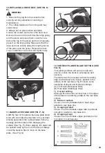
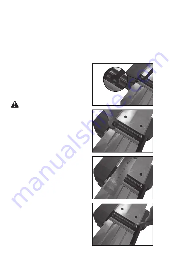
9. BLADE FITTING AND CHANGING (SEE FIG. 

J, K, L, M)

NOTE: 

Dull and worn blade cannot be reground 

and must be replaced. Always replace blades in 

pairs.


WARNING: 

Remove power cord from the 

socket before carrying out any adjustments 

or changing blades. Always put on gloves when 

replacing blades.

Using the blade spanner provided to loosen 

the three installation screws approximately 1/2 

rotation anticlockwise.

NOTE:

 Do not over-loosen the screws. If the 

screws are too loose, the alignment of the new 

blade will not be accurate.

Before removing the old blades, take notice of 

the direction of cut as well as how the tapered 

edge of the old blades are oriented. The tapered 

edge of the new blades must be in the same 

orientation as the original blades.

Press the safety cover down with your finger. 

Push the blade out with the tip of a spanner (or a 

screwdriver) and then remove. 

NOTE:

 There is no need to remove the blade 

clamp as this will change the factory settings for 

cutting blade height control. 

NOTE: 

If a blade cannot be pushed out easily 

after loosening the screws, use a piece of wood 

to break the blade loose from the blade clamp, 

with a short sharp blow. Then push with a 

screwdriver to remove the blades. If necessary, 

tap the piece of wood sharply with a small 

hammer to break the blades loose.

Before reinserting a new or reverse blade, 

always clean both the blade and the blade 

seat if dirty. Slide the blade into the clamp with 

a spanner (or a screwdriver) in the correct 

orientation. Check the blade is equal with the 

clamp. Retighten the three blade screws with the 

spanner. 

Repeat the above procedure to change the other 

blade.

After the blades are replaced, check if the blades 

are parallel and in the same surface as the rear 

base plate with a ruler. If not, you can adjust 

the blades with the hexagonal wrench provided. 

Firstly loosen the three screws on the blade 

clamp. Turn the socket head screw clockwise, 

the blade will be risen. Turn it anticlockwise, the 

blade will be lowered down. Finally retighten the 

three screws fully.

13

2

1

9

11

7

12

45

o

11

14

b

a

15 16

17

20

18

19

D

E

F

G

H

I

J

K

L

M

N

O

P

Q

R

B

C

A

Содержание CR900NM

Страница 1: ......

Страница 2: ...Instrucciones en Español Instruções no Portugués Instructions in English ...

Страница 3: ...3 3 2 1 4 6 11 14 10 8 7 9 12 13 5 17 ...

Страница 4: ...n conformidad con la norma EN 60745 Valor de emisión de vibraciones ah 4 789 m s2 Incertidumbre K 1 5 m s El valor de vibración total declarado puede utilizarse para comparar una herramienta con otra y LISTA DE COMPONENTES 1 Interruptor de encendido apagado 2 Interruptor de bloqueo 3 Área del mango 4 Tapa de extracción de polvo 5 Tapa de la banda 6 Tornillo de fijación 7 Guía paralela 8 Base del p...

Страница 5: ...SIEMPRE brocas cuchillas y cinceles bien afilados Mantenga la herramienta de acuerdo a estas instrucciones y bien lubricada donde sea necesario Si la herramienta va a utilizarse regularmente invierta en accesorios para atenuar la vibración No utilice las herramientas a temperaturas de 10 C o menos Planifique su trabajo para espaciar el uso de las herramientas de alta vibración a lo largo de varios...

Страница 6: ...a 3 Seguridad personal a Manténgase alerta observe qué hace en cada momento y utilice el sentido común cuando utilice una herramienta eléctrica No utilice una herramienta eléctrica si está cansado o bajo los efectos de drogas alcohol o medicación Un momento de falta de atención mientras utiliza herramientas eléctricas puede ocasionar graves lesiones b Utilice equipo de protección personal Utilice ...

Страница 7: ...nos y son más fáciles de controlar g Utilice la herramienta eléctrica los accesorios las brocas y puntas etc de acuerdo a estas instrucciones teniendo en cuenta las condiciones de trabajo y la tarea que debe realizar El uso de la herramienta eléctrica para realizar trabajos distintos a los que está destinada puede ocasionar situaciones peligrosas 5 Servicio a La reparación de la herramienta debe r...

Страница 8: ...n para los oídos Utilice protección para los ojos Utilice mascarilla Doble aislamiento Advertencia Los productos eléctricos no deben tirarse junto a los residuos domésticos Deposítelos en un punto de reciclaje Consulte a las autoridades locales o los comercios minoristas si necesita información sobre reciclaje ...

Страница 9: ...urarse de que el cepillo quita la cantidad de madera deseada NOTA Para proteger las cuchillas durante el almacenamiento transporte etc configure a 0 la rueda de ajuste de profundidad de la cuchilla 13 1 9 11 7 12 45o D E F B C 3 CEPILLADO DE SUPERFICIES ESTÁNDAR VER FIG C Ajuste la profundidad de corte deseada Coloque la parte frontal de la base del patín sobre la superficie de trabajo de forma to...

Страница 10: ... carcasa El ajuste de la profundidad de corte puede definirse desde 0 a 10 mm Para ajustar la profundidad de corte coloque el cepillo en un tablón plano A continuación afloje el tornillo y deslice la guía de ajuste de profundidad de corte hacia arriba y abajo hasta lograr la profundidad deseada Apriete el tornillo de cierre manual completamente 11 7 11 14 b a 15 16 17 E F G H I J 7 REBAJE VER FIG ...

Страница 11: ...í como de la orientación del borde estrecho en las cuchillas viejas El borde estrecho de las cuchillas nuevas debe seguir la misma orientación que las cuchillas originales Presione la tapa de seguridad con el dedo Empuje la cuchilla hacia afuera a con la punta de la llave o un destornillador y retírela Nota No hay necesidad de quitar la sujeción de la cuchilla ya que se cambiarían los ajustes de f...

Страница 12: ... la tapa y ajústelo completamente 14 15 16 17 I J K L M N 20 18 19 N O P Q R 11 SOPORTE DE LA BASE DEL PATÍN VER FIG P Q Levante la parte posterior del cepillo la rueda de soporte de la base del patín 20 puede hacer que la herramienta se asiente evitar que las cuchillas de corte se dañen y que estas dañen la superficie Ver Fig P Cuando cepille el soporte se verá empujado por el extremo de la mader...

Страница 13: ...enta eléctrica no necesita lubricación ni mantenimiento Todas las partes de la herramienta eléctrica deben enviarse a reparar a un especialista autorizado Nunca utilice agua o detergentes químicos para limpiar la herramienta Límpiela con un paño seco Guarde la herramienta en un lugar seco Mantenga limpias las ranuras de ventilación del motor No deje que se acumule polvo en los elementos de control...

Страница 14: ...ato será reparado o reemplazado por uno nuevo de igual o mayor valor según nuestro criterio Esta garantía no es válida por defectos causados como resultado de 1 Mal uso abuso o negligencia 2 Uso profesional 3 Intento de reparación por personal no autorizado 4 Daños causados por accesorios y objetos externos sustancias o accidentes EHLIS S A NIF A 08014813 c Sevilla s n Polígon Industrial Nord Est ...

Страница 15: ...15 ...

Страница 16: ...993X216 PPL900GH 1 30 1 31 7993X216 PPL900GH 1 31 4 32 7993X216 PPL900GH 1 32 1 33 7993X216 PPL900GH 1 33 1 34 7993X216 PPL900GH 1 34 1 35 7993X216 PPL900GH 1 35 1 36 7993X216 PPL900GH 1 36 1 37 7993X216 PPL900GH 1 37 1 38 7993X216 PPL900GH 1 38 1 39 7993X216 PPL900GH 1 39 1 40 7993X216 PPL900GH 1 40 1 41 7993X216 PPL900GH 1 41 1 42 7993X216 PPL900GH 1 42 1 Position No Part Number Qty 43 7993X216 ...

Страница 17: ...17 3 2 1 4 6 11 14 10 8 7 9 12 13 5 17 ...

Страница 18: ... totais das vibrações soma triaxial de vetores estão em conformidade com a norma EN 60745 Valor da emissão de vibrações ah 4 789 m s2 Incerteza K 1 5 m s LISTA DE COMPONENTES 1 Botão Ligar Desligar 2 Botão de segurança 3 Áreas de agarre da mão 4 Tampa para a saída do pó 5 Capa de proteção da correia 6 Parafuso de aperto 7 Guia paralela 8 Placa da base 9 Ranhuras em V 10 Guia de rebaixo 11 Parafuso...

Страница 19: ...gada mas na verdade não está a realizar o trabalho Tal pode reduzir consideravelmente o nível de exposição ao longo do período total de trabalho Ajudar a minimizar o risco de exposição às vibrações Use SEMPRE cinzeis brocas e lâminas afiados Faça a manutenção desta ferramenta de acordo com as presentes instruções e mantenha a bem lubrificada se aplicável Se utilizar a ferramenta de forma regular n...

Страница 20: ...ara uso no exterior Usar uma extensão indicada para utilização no exterior reduz o risco de choque elétrico f Se tiver mesmo que utilizar uma ferramenta elétrica num lugar húmido utilize uma fonte de alimentação com proteção mediante um dispositivo de corrente residual RCD Usar um dispositivo de corrente residual RCD reduz o risco de choque elétrico 3 Segurança pessoal a Mantenha se alerta esteja ...

Страница 21: ...es derivam de uma manutenção pobre das ferramentas elétricas f Mantenha as ferramentas de corte afiadas e limpas Se a manutenção das ferramentas de corte de arestas afiadas for apropriada a probabilidade de estas ficarem presas é menor e são mais fáceis controlar g Utilize a ferramenta elétrica os acessórios e as brocas etc de acordo com as presentes instruções tendo em consideração as condições d...

Страница 22: ...otección para los ojos Use uma máscara de proteção contra o pó Isolamento duplo Aviso Os resíduos dos produtos elétricos não devem ser eliminados juntamente com os resíduos domésticos Por favor recicle sempre que haja pontos de recolha Consulte as Autoridades Locais ou o distribuidor para obter informações sobre reciclagem ...

Страница 23: ...ra garantir que a plaina remove a quantidade pretendida de madeira NOTA De modo a proteger as lâminas durante o armazenamento transporte etc coloque o manípulo de profundidade de corte em 0 13 1 9 11 7 12 45o D E F B C 3 APLAINAÇÃO NORMAL DA SUPERFÍCIE VER FIG C Defina a profundidade de corte pretendida Coloque a parte da frente da placa de base estável sobre a superfície de trabalho Certifique se...

Страница 24: ...o 11 fornecido na abertura do Rebaixo Coloque o parafuso na porca localizada na caixa do motor É possível estabelecer uma profundidade entre os 0 e os 10 mm Para definir a profundidade de corte coloque a plaina sobre uma tábua lisa depois desaperte o parafuso e deslize a guia de ajuste da profundidade de corte para cima e para baixo até conseguir a profundidade pretendida Aperte completamente o pa...

Страница 25: ...o fio de corte das lâminas antigas O fio de corte das lâminas novas deve estar na mesma orientação das lâminas originais Pressione com o dedo a tampa de segurança para baixo Puxe a lâmina com a ponta da chave ou chave de fendas para fora e depois retire a Nota Não é necessário remover o grampo da lâmina dado que isso alteraria a configuração de fábrica do controlo da altura da lâmina Nota Se não c...

Страница 26: ...o Coloque o parafuso da tampa e aperte o totalmente 14 15 16 17 I J K L M N 20 18 19 N O P Q R 11 SUPORTE DA PLACA DA BASE VER FIG P Q Levante a parte de trás da plaina o manípulo de suporte da placa da base 20 permite pousar diretamente a máquina protege as lâminas de eventuais danos e protege a superfície evitando danos causados pelas lâminas Ver Fig P Ao aplainar o suporte será empurrado para a...

Страница 27: ...nta elétrica não requer lubrificação adicional nem manutenção Esta ferramenta elétrica não contém nenhuma peça que possa ser reparada pelo utilizador Nunca use água ou produtos de limpeza químicos para limpar a ferramenta Limpe com um pano seco Guarde sempre a máquina num local seco Mantenha as ranhuras de ventilação do motor limpas Mantenha todos os botões de utilização isentos de pó Ocasionalmen...

Страница 28: ...superior de acordo com o nosso critério Esta garantia é nula se os defeitos forem causados por 1 Má utilização abuso ou negligência 2 Utilização profissional 3 Reparos anteriores feitos em centros de assistência técnica não autorizados 4 Danos causados por objeitos estranhos ao produto substâncias ou acidente EHLIS S A NIF A 08014813 c Sevilla s n Polígon Industrial Nord Est 08740 Sant Andreu de l...

Страница 29: ...29 ...

Страница 30: ...993X216 PPL900GH 1 30 1 31 7993X216 PPL900GH 1 31 4 32 7993X216 PPL900GH 1 32 1 33 7993X216 PPL900GH 1 33 1 34 7993X216 PPL900GH 1 34 1 35 7993X216 PPL900GH 1 35 1 36 7993X216 PPL900GH 1 36 1 37 7993X216 PPL900GH 1 37 1 38 7993X216 PPL900GH 1 38 1 39 7993X216 PPL900GH 1 39 1 40 7993X216 PPL900GH 1 40 1 41 7993X216 PPL900GH 1 41 1 42 7993X216 PPL900GH 1 42 1 Position No Part Number Qty 43 7993X216 ...

Страница 31: ...31 3 2 1 4 6 11 14 10 8 7 9 12 13 5 17 ...

Страница 32: ...protection VIBRATION INFORMATION Vibration total values triax vector sum determined according to EN 60745 Vibration emission value ah 4 789 m s2 Uncertainty K 1 5 m s COMPONENT LIST 1 On off switch 2 Lock off switch 3 Hand grip areas 4 Dust extraction cover 5 Belt cover 6 Fastening screw 7 Parallel guide 8 Base plate 9 V grooves 10 Rebate guide 11 Rebate guide fastening screw 12 Cutting depth Scal...

Страница 33: ...tool in accordance with these instructions and keep well lubricated where appropriate If the tool is to be used regularly then invest in anti vibration accessories Avoid using tools in temperatures of 100 C or less Plan your work schedule to spread any high vibration tool use across a number of days ACCESSORIES Parallel guide 1 Rebate guide 1 Blades on machine 2 Spanner 1 Dust bag 1 We recommend t...

Страница 34: ...the switch on invites accidents d Remove any adjusting key or wrench before turning the power tool on A wrench or a key left attached to a rotating part of the power tool may result in personal injury e Do not overreach Keep proper footing and balance at all times This enables better control of the power tool in unexpected situations f Dress properly Do not wear loose clothing or jewellery Keep yo...

Страница 35: ...sing guard 2 Hold the power tool by insulated gripping surfaces only because the cutter may contact its own cord Cutting a live wire may make exposed metal parts of the power tool live and could give the operator an electric shock 3 Use clamps or another practical way to secure and support the workpiece to a stable platform Holding the work by your hand or against the body leaves it unstable and m...

Страница 36: ...justment knob to 0 13 1 9 11 7 12 45o D E F B C 3 STANDARD SURFACE PLANING SEE FIG C Set the desired cutting depth Position the front part of the base plate flat onto the work surface Make sure that the blades are not touching the workpiece Switch the machine on and push your planer forward and it will start cutting Always maintain all of the base plate flat on the work surface to prevent the cutt...

Страница 37: ...to 10mm To adjust the depth of cut place the planer on a flat board then loosen the screw and slide the cut depth adjustment guide up and down for required depth Tighten the thumb screw fully 11 7 11 14 b a 15 16 17 F G H I J 7 REBATING SEE FIG H The width of rebating cut a is adjustable by moving the parallel guide The depth of rebating cut b is determined by moving the Rebate and the number of p...

Страница 38: ...the old blades are oriented The tapered edge of the new blades must be in the same orientation as the original blades Press the safety cover down with your finger Push the blade out with the tip of a spanner or a screwdriver and then remove NOTE There is no need to remove the blade clamp as this will change the factory settings for cutting blade height control NOTE If a blade cannot be pushed out ...

Страница 39: ...amage and the blades from damaging the surface See Fig P When planing the stand will be pushed away by the end of the wood Always check the stand is free to move on the base plate See Fig Q 20 18 19 O P Q R 12 CORRECT PLANER BLADE SETTING SEE FIG R Your planing surface will end up rough and uneven unless the blade is set properly and securely The blade must be mounted so that the cutting edge is a...

Страница 40: ...cts must not be disposed of with household waste Please recycle where facilities exist Check with your local authorities or retailer for recycling advice GUARANTEE This product has been manufactured to the highest standards It is guaranteed against faulty materials and workmanship for at least 24 months from purchase Please keep your receipt as proof of purchase If the product is found to be defec...

Страница 41: ...ion Electric Planer Type Designation CR900NM PL designation of machinery representative of planer Function removing surface material with a rotating cutter Complies with the following Directives 2006 42 EC 2014 30 EU 2011 65 EU Standards conform to EN 60745 1 EN 60745 2 14 EN 55014 1 EN 55014 2 EN 61000 3 2 EN 61000 3 3 Date 12 12 2016 Company name Ehlis S A CEO Alejandro Ehlis ...

Страница 42: ...42 ...

Страница 43: ...993X216 PPL900GH 1 30 1 31 7993X216 PPL900GH 1 31 4 32 7993X216 PPL900GH 1 32 1 33 7993X216 PPL900GH 1 33 1 34 7993X216 PPL900GH 1 34 1 35 7993X216 PPL900GH 1 35 1 36 7993X216 PPL900GH 1 36 1 37 7993X216 PPL900GH 1 37 1 38 7993X216 PPL900GH 1 38 1 39 7993X216 PPL900GH 1 39 1 40 7993X216 PPL900GH 1 40 1 41 7993X216 PPL900GH 1 41 1 42 7993X216 PPL900GH 1 42 1 Position No Part Number Qty 43 7993X216 ...

Страница 44: ......

Отзывы: