background image

Page 13

SmartRescue Specifications

Conforms to UL STD 2017

Type of Signaling:

• Emergency Signaling, TYPE AM

Protection:

• Short Circuit/Overload/Over Voltage

Ratings for SmartRescue Base Stations:

• Input Ratings: 100-120vac, 50/60Hz, 4.0A or 200-240vac, 50/60Hz, 2.0A when powered by 2500-PWR24U


• Output Rating: 24vdc, 5A

• Input Ratings: 100-240vac, 50/60Hz, 0.7A when powered by RP7300061


• Output Rating: 24vdc, 1.1A

• Input Ratings: 100-240vac, 50/60Hz, 0.65A when powered by RP7300055


• Output Rating: 24vdc, 1.04A

Ratings for 2100 Series SmartPhones:

• 24vdc, 0.5A when powered by 2500-PWR24U

• 24vac, 5VA when powered by RP7300110

Environmental:

• For indoor use only

• Operating temperature 32° F to 120° F (0° C to 49° C)

TB1 Relay:

• Load Current: 130mA

• Load Voltage: 350vdc or vac

Note: 

Input power circuit, battery circuit, and phone circuits are supervised in accordance with UL 2017 Section 84.3.

Rechargeable Battery Ratings:
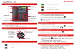
SmartPhone

• Voltage: 7.2V

• Max Circuit Current: 80mA

• Amp Hour Capacity: 1300mAh

• Expected Standby Time: 24 hours

• Replacement Part: RP7300110

SmartRescue

• Voltage: 16.8V

• Max Circuit Current: 100mA

• Amp Hour Capacity: 1400mAh

• Expected Standby Time: 24 hours

• Replacement Part: RP7300109A
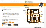
Model Number

5 Zone

10 Zone

Stainless Steel

Enclosure

Powder Coated

Steel Enclosure

Surface Mount

Flush Mount

2500-205D

X

X

X

2500-210D

X

X

X

2500-205PSS

X

X

X

2500-210PSS

X

X

X

2500-205B

X

X

X

2500-210B

X

X

X

2500-205FM

X

X

X

2500-210FM

X

X

X

SmartRescues

Models & Differences

Содержание 2500-205D

Страница 1: ...SmartRescue 5 10 Installation Operations Manual N56W24720 N Corporate Circle Sussex WI 53089 800 451 1460 www rathcommunications com RP8500510 Ver 4 11 19 WARRANTY 2YEAR...

Страница 2: ...ations com Table of Contents SmartRescue 5 10 Installation Powering the SmartRescue Wiring Emergency Phones to SmartRescue Typical Wiring Diagrams for Elevators Typical Wiring Diagram for Areas of Ref...

Страница 3: ...s Pre Installation Requirements Step 1 Remove the front cover from the SmartRescue and mount the SmartRescue back box to the wall using suitable mounting screws not included Step 2 Punch out the condu...

Страница 4: ...d 120vac outlet Option 2 Hard Wired Transformer Connect the hot wire of the 120vac to the L screw Connect the neutral wire of the 120vac to the N screw Connect the ground wire of the 120vac to the gro...

Страница 5: ...phone line is 600 ohms Step 7 Mount the front cover back on to the enclosure Emergency Phone Yellow PIN 1 Green PIN 2 Red PIN 3 Black PIN 4 Diagram B 0 2 5 3 1 4 6 7 8 9 0 2 5 3 1 4 6 7 8 9 0 2 5 3 1...

Страница 6: ...SPECIFIC PHONE IF THE GREEN LED IS LIT YOU WILL JOIN CONVERSATION 6 PRESS TALK HOLD BUTTON AGAIN TO PLACE CONVERSATION ON HOLD 7 PRESS RED DISCONNECT CALL TO RESCUE SERVICES BUTTON TO END EXTERNAL CAL...

Страница 7: ...HOLD 7 PRESS RED DISCONNECT CALL TO RESCUE SERVICES BUTTON TO END EXTERNAL CALL ANY PHONE AND SUB MASTER ORIGINALLY TALKING REMAIN IN CONVERSATION WITH THIS UNIT 8 HANG UP HANDSET TO END CALLS TO PHON...

Страница 8: ...VED EMERGENCY PHONE SOLID LIGHT C ALLING BLINKING LIGHT RECEIVED EMERGENCY PHONE SOLID LIGHT C ALLING BLINKING LIGHT RECEIVED EMERGENCY PHONE Typical Wiring Diagram for Area of Refuge Applications 1 P...

Страница 9: ...rgency Number as entered in b Stop 4 To exit program mode press and hold Stop for 2 3 seconds until warble sound Program the Location Message Note This is always done unless your Call Center requests...

Страница 10: ...hone that placed the call c If call is not answered at the SmartRescue the Emergency Phone will hang up and dial the second number programmed into the phone d The Rescue Services LED located next to t...

Страница 11: ...6 9 TB1 Relay SmartRescue System Activation Relay When an Emergency Phone has been activated this relay changes from NO to closed It can be connected to a strobe or other notification means Connectio...

Страница 12: ...SmartPhone is correct Two way communication from SmartPhone is poor There could be feedback on the line Adjust the VR1 and VR2 Verify wiring is not spliced onto the phone line cord SmartRescue will n...

Страница 13: ...or indoor use only Operating temperature 32 F to 120 F 0 C to 49 C TB1 Relay Load Current 130mA Load Voltage 350vdc or vac Note Input power circuit battery circuit and phone circuits are supervised in...

Страница 14: ...61 294 96 1 03 26 25 1 27 32 38 0 32 8 05 0 88 22 23 4 34 110 17 0 45 11 41 0 50 12 70 1 0 56 319 09 11 61 294 96 0 33 8 49 5 81 147 48 0 28 7 18 FRONT PANEL COVER LEFT SIDE BOTTOM SIDE CONTROL INSIDE...

Страница 15: ...ED Y G R B Y G R B Y G R B Y G R B Y G R B Y G R B Y G R B Y G R B Y G R B Y G R B 1 2 3 4 5 6 7 8 9 10 HOOK SWITCH Y G R B Y G R B 0 69 17 50 0 84 21 27 0 69 17 46 0 69 17 46 0 25 6 35 0 13 3 18 4 02...

Отзывы: